


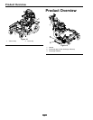
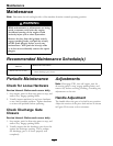
Setup
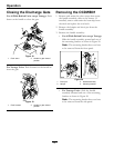
Figure 5
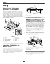
1. Latch 3. Front pin
2. OCDWB01 assembly 4. Slot
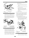
• If the front pin does not engage in the slot
in the deck, loosen or completely remove the
hardware in the gate link frame as shown in
Figure 6. Position the gate link frame so that
the front pin aligns with the slot. Reinstall
hardware, if removed, and tighten. Pivot the
assembly towards the deck and engage the
front pin into the slot.
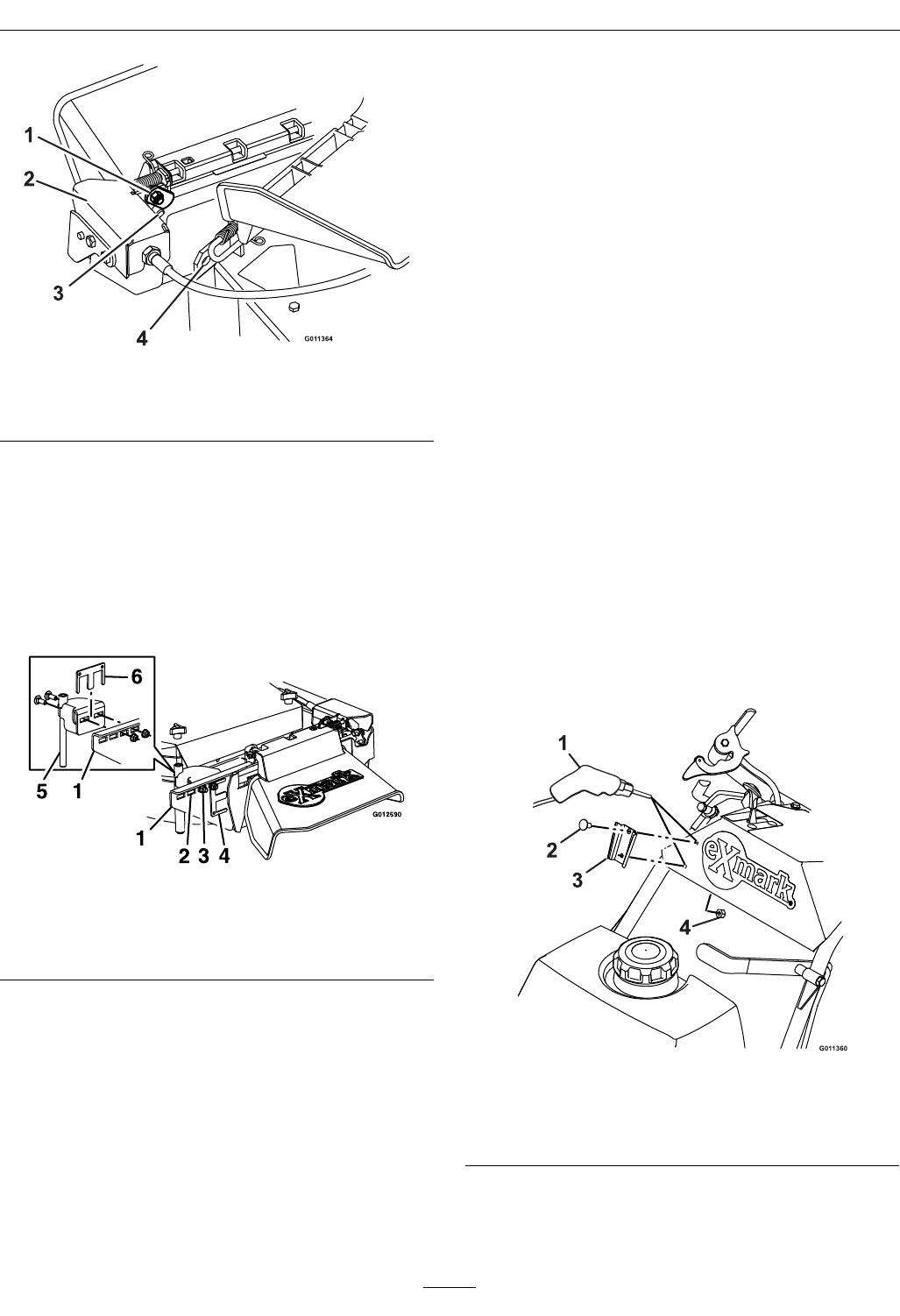
Figure 6
1. Gate link frame 4. Shim (storage position)
2. Adjustment slots 5. Pivot mount assembly
3. Hardware
6. Shim (installed position)
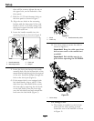
• Due to manufacturing variance, the gate
link frame may not close and have complete
contact all around the discharge opening.
Any gaps are to be minimized. If the rear of
the gate link frame contacts the mower deck
while rotating it towards the deck creating a
gap at the front, use the steps below to install
a shim. If the gate link frame has complete
contact all around the discharge opening, the
shim is not necessary. It can remain in the
storage position for potential later use on
other mower decks.
A. Remove the shim located on the front of
the gate link frame and loosely reinstall
the nut.
B. Loosen the nut on the left adjustment slot
of the gate link frame.
C. Install the shim between the gate link
frame and the pivot mount assembly.
Position the center tab of the shim
between the two mounting bolts as shown
in Figure 6.
D. Tighten hardware.
4. Rotate the latch downward to lock the assembly
in this position (reference Figure 5). Adjust the
tension on the latch to hold the assembly up to
the deck, yet allow for release by hand. Tension
can be adjusted by tightening or loosening the
hardware that retains the latch.
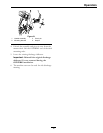
5. Install the mounting bracket to the unit.
• For all Walk-Behind Units except Vantage:
A. Position the mounting bracket vertically,
with the wide opening of the bracket
pointed upward, and install on the front of
the unit as shown in Figure 7.
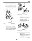
Figure 7
1. Drill 3. Mounting bracket
2. 5/16-18 x 5/8 inch
carriage bolt
4. 5/16 inch nyloc nut
B. Using the mounting bracket as a template,
mark the two hole locations on the front
panel of the unit (see Figure 7). Make sure
9