


- 28 -
j) Recheck that blocks fit just snugly under the deck skirt and that the
tension on all the chains are approximately equal. Make sure all chain
attachment bolts are tight.
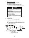
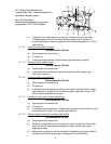
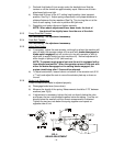
k) Raise deck lift lever to the 4.5” cutting height position (also transport
position, See Fig 5. Adjust spring compression until proper distance is
obtained between the two washers (See Fig 7) by turning the nut at the
front of each spring. Lock nuts in position with jam nuts.
l) Reposition anti-scalp rollers and tighten securely.
NOTE: When above adjustments have been made, the front of
the deck will be slightly lower than the rear of the deck.
5.2.3 Pump Drive Belt Tension.
Self-tensioning - No adjustment necessary.
5.2.4 Deck Belt Tension.
Self-tensioning - No adjustment necessary.
5.2.5 Adjust Seat Switch.
a) If necessary, adjust the seat actuator rod length to where the machine will
shut off when the operator raises off the seat (with
brake disengaged
or
blade switch engaged
) but will continue to run with operator in seat (a
slight shift in weight should not shut machine off). Normal adjustment is
when length of spring is 2.09” (with seat up).
NOTE: To prevent rough ground cut-outs the unit is equipped with a
time delayed seat switch. When the operator raises off the seat with
either the brake disengaged or the cutting blades engaged, the
engine should stop after 1/2 second has elapsed.
b) To adjust seat switch, loosen locknut on bottom of the actuator rod (5/16
x 7” bolt) and adjust the nuts to move the actuator plate up or down on
the rod.
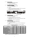
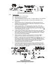
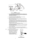
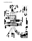
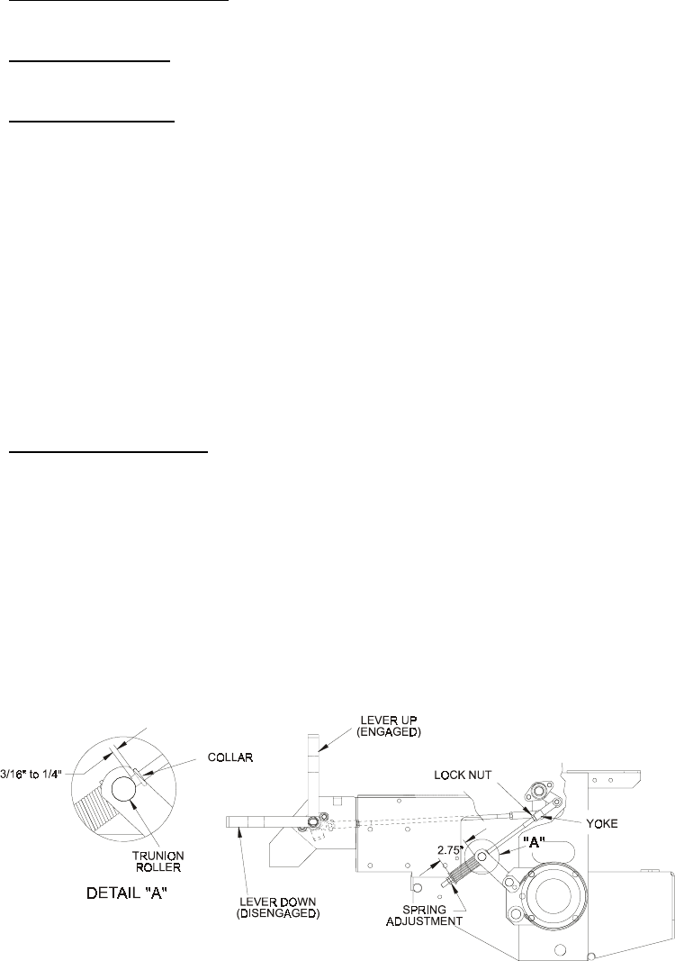
5.2.6 Brake Link Adjustment.
Check to make sure brake is adjusted properly.
a) Disengage brake lever (lever down).
b) Measure the length of the spring. Measurement should be 2.75” between
washers (see Fig 8).
c) If adjustment is necessary, tighten the lock nut directly below the yoke
and loosen the two nuts jammed together below the spring. Turn the nut
directly below the washer until the correct measurement is obtained.
Tighten the two jam nuts below the spring together and repeat on
opposite side of unit.
BRAKE ADJUSTMENT
FIG. 8