


- 11 -
2.10.4 Tread Width: (center to center of tires, widthwise)
w/44” Deck w/48” Deck w/52” Deck
Drive Wheels
34.4 in. (87.4 cm) 36.4 in. (92.5 cm) 38.4 in. (97.5 cm)
Front Casters
32.2 in. (81.8 cm) 32.2 in. (81.8 cm) 34.6 in. (87.9 cm)
2.10.5 Wheel Base: (center of caster tire to center of drive tire)
w/44” & 48” Deck: 45.9 in. (116.6 cm)
w/52” Deck: 47.2 in. (119.9cm)
2.10.6 Curb Weight
*
: w/44” Deck: 887 lbs. (403.2 kg)
w/48” Deck: 907 lbs. (412.3 kg)
w/52” Deck: 1025 lbs. (464.9 kg)
* Note: Weight will vary slightly, depending on engine option.
2.11 TORQUE REQUIREMENTS
Bolt Location Torque Bolt Location Torque
Cutter Housing Spindle Nut ......... 75-80 ft-lbs.
Blade Mounting Bolt .................... 75-80 ft-lbs.
Engine Deck/Front Frame Mount. 30-35 ft-lbs.
Anti-Scalp Roller Bolts ................. 40-45 ft-lbs.
Engine Mounting Bolts ................25-30 ft-lbs.
Wheel Motor Mounting Bolts........72-77 ft-lbs.
Wheel Hub Slotted Nut.... minimum125 ft-lbs.
3. ASSEMBLY INSTRUCTIONS
3.1 UNCRATE MOWER
3.2 INSTALL DRIVE WHEELS
.
3.2.1 Mount drive wheels with the valve stem to the outside of the unit. Secure using
four (4) 1/2-20 x 7/8”UNF wheel bolts (installed in hubs) or 1/2-20 wheel nuts
(installed on studs in hubs) for each wheel. Torque to 95 ft-lbs (128 N!M).
NOTE: Earlier models require the UNF wheel bolts. Later models have studs
installed in the wheel hub and require wheel nuts.
3.3 CHECK TIRE PRESSURE.
3.3.1 Check tire pressure in caster and drive tires. Proper inflation pressure for all
four (4) tires is 13 psi (90 kPa). Adjust if necessary.
3.4 INSTALL SEAT RETAINING ROD
.
3.4.1 Tilt seat up. Remove 5/16” nylock nut from bolt attaching seat retaining rod to
seat frame. Remove ignition keys attached to bolt. Remove retaining rod from
seat and insert the “L” shaped end of the rod into the hole directly above the
left-side hydraulic pump (the “L” must be positioned to the left or pointing up).
Position the seat retaining rod to the outside of the mounting tab on the seat
frame and secure with 5/16” x 1” bolt and nyloc nut. Tighten until snug, then
loosen just enough so the rod pivots freely.
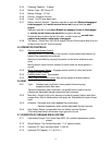
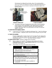
3.5 INSTALL MOTION CONTROL LEVERS
.
3.5.1 Loosen and remove the two (2) 3/8” x 1” bolts and spring disc washers which
attach the motion control levers to the control arm shafts for shipping and the
two (2) 3/8” x 1” bolts and spring disc washers which are screwed into the
control arm shafts.
a) Install the left motion control lever onto the control arm shaft (See Fig 1)
on the left side of the console. Place the lever (with the mounting plate
towards the rear) on the
outside
of the control arm shaft and secure with
the bolts and washers. Position the lever so the bolts are in the center of
the slots on the lever mounting plate and tighten until snug. Repeat on
opposite side of unit.