


10
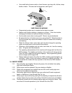
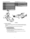
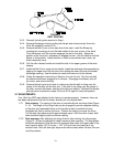
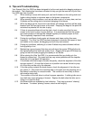
FIGURE 8
BELT ROUTING
3.6.3. Reinstall the belt guide removed in Step 1.
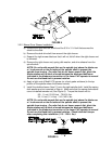
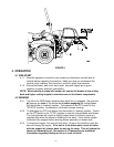
3.6.4. Remove Discharge chute by pulling the hairpin and chute pivot pin (from the
Drive Kit installed in section 3.2).
3.6.5. Remove the Belt Cover on the right side of the deck. Install the Blower by
inserting the mounting pin into the tube welded to the rear corner of the deck.
Pivot the blower until the front pin engages the slot in the deck. Adjust the
position of the front pin if necessary to engage the slot. Use the latch to lock the
blower in this position. Adjust tension on latch to draw blower up to deck, yet
allow release by hand.
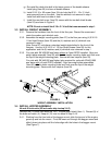
3.6.6. Pull the idler release handle and install the belt in the upper groove of the deck
sheave.
3.6.7. Install the Belt Cover using the two knobs. Install the discharge tube assembly by
slipping the upper end into the hood, then sliding the lower end over the blower
discharge opening. Use the latches to retain the lower end to the blower.
3.6.8. Follow the operation instructions in Section 4 to run the unit. Run the unit with
the blades and blower engaged for 2 minutes. Disengage the blades, shut off
the motor, and remove the key.
3.6.9. Remove the belt cover and check to make sure that the belt is riding near the
center of the flat idler on the idler arm. If the belt is not riding near the center of
the idler, remove the blower, and bend the idler arm slightly. Reinstall the blower
and belt cover and perform steps 3.6.8 and 3.6.9 again to verify belt position.
3.7 ADJUSTMENTS:
Your Ultra Vac QDS was adjusted at the factory to operate properly. However, there are
two basic adjustments that can be made, should your unit require them:
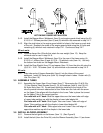
3.7.1 Door closing: The closing of the door is controlled by the two hinge links (Figure
9 – A). The length of the hinge links can be changed to provide complete closing
of the door and reasonable force on the handle to latch or unlatch the door.
Lengthen the links to reduce the force. Shorten the links to increase the force.
The left and right sides must be approximately equal. With the door closed, both
links should be slightly tight to minimize rattling.
3.7.2 Door opening: After adjusting the hinge links for door closing, the hinge stops
(Figure 9 – B) can be adjusted to obtain maximum door opening. The stop plates
should be adjusted so that the door link contacts them when the upper tube of the
door frame is within .25” (6.4 mm) ± .125” (3.2 mm) from the lower lip of the
molded hood. Both left and right stops must make contact when the door link arm
is at this position.