


9
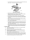
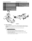
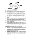
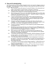
FIGURE 7
HOT ENGINE GUARD INSTALLATION
3.4.2. Install the Bagger Mount Weldment (Item 2) and engine guard shield using the (8)
5/16-18 x 1 Screws provided (Item 3) and (8) whizlock nuts removed in step 3.4.1.
3.4.3. Align the side holes in the engine guard shield to holes in the frame on each side
of the unit. Reattach the sides of the engine guard shield using the (4) bolts and
remaining (4) whizlock nuts retained in step 3.4.1. Continue at step 3.4.7.
52 inch units
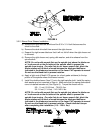
3.4.4. Remove discard the (8) bolts that retain the rear weight (Item 12). Keep the
whizlock nuts for use in step 3.4.6.
3.4.5. Install the Bagger Mount Weldment (Item 2) to the rear of the frame using (4)
5/16-18 x 1 screws (Item 3) and (4) 5/16 – 18 whizlock nuts (Item 14). Use only
the bottom four holes on the Bagger Mount Weldment
3.4.6. Install the Rear Weight (Item 12) and spacer (Item 13) from the drive kit using the
(8) 5/16 – 18 X1.75 screws (Item 14) and whizlock nuts removed in step 3.4.4.
All units
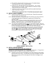
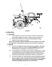
3.4.7. Slide tube ends of Hopper Assembly (Item 4) into the tubes of the mount
weldment. Install (2) clevis pins (Item 15) through holes in tubes. Retain with (2)
Hair Pins (Item 16).
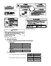
3.5 ASSEMBLE TUBES
3.5.1. Assemble the Upper (Item 6) and Lower (Item 7) Tubes using the (3) #10-24 x
.75 Hex Washer Head Screws (Item 8), (3) #10 washers (Item 9), and (3) #10-
24 Nyloc Nuts (Item 10). Screw head should be installed to the inside of the
tube to provide minimum obstruction to flow. Make sure the hole with the arrow
on the Upper Tube aligns with the dimple in the Lower Tube to place the turnout
on the Upper Tube in the correct position.
For units with a 44” deck: Slide the upper tube over the lower tube until edge
of upper tube matches up with the dimple in lower tube labeled 44.
For units with a 48” deck: Slide Upper Tube over Lower Tube until edge of
Upper Tube matches up with the dimple in lower tube labeled 48.
For units with a 52” deck: Slide upper tube over Lower Tube until edge of
upper tube matches up with the dimple in the lower tube
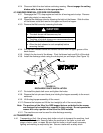
3.6 INSTALL BLOWER ASSEMBLY
3.6.1. Remove the belt guide on the blower (Item 11). (See Figure 8)
3.6.2. Install the belt (from the Drive Kit) onto the Blower Assembly (Item 11) as shown.