


8
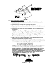
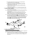
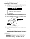
g) Re-install the deck drive belt in the lower groove of the double sheave.
Install plug (Item 25) into bore of double sheave.
h) Install 5/16-18 x .62 screw (Item 24) into hole that 5/16 – 18 x 3 ¼ bolt
was removed from on the deck. Use the whizlock nut removed in step 1.
Install bolt with head to inside of deck.
i) Install the new belt cover (Item 23) secure with the two belt shield knobs
(Item 20) as shown in Figure 3.
NOTE: Do not re-install the 5/16 x 3 1/4 bolt that was removed in step 1.
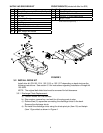
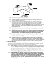
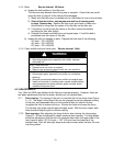
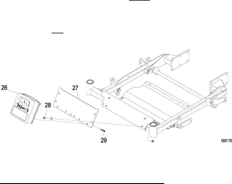
3.3 INSTALL WEIGHT ASSEMBLY
3.3.1. Remove the hardware from the front of the floor pan. Discard the screws and
retain the washer and whizlock nuts.
3.3.2. Assemble the weight mounting plate (Item 27) to the floor pan using (4) 5/16-18
1 Hex Head Screws (Item 28) and the (4) washers and (4) whizlock nuts
removed in step 1.
Note: Some 52” units have a standard weight plate bolted to the front of the
floorpan. Use the (4) 5/16-18 x 11/2 Hex Head Screws (Item 28) for this
application. and the (4) washers and (4) whizlock nuts removed in step 1
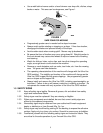
3.3.3 For units with SN 439,999 and lower without
a 2 post ROPS installed: Align one
weight plate assembly (Item 26) with the two center mounting holes and hook over
the top of the weight mounting plate. Secure with two hairpins (Item 29).
For units with SN 440,000 and higher (also required for units with SN 439,999
and lower with
a 2 post ROPS installed): Align two weight plate assemblies
(Item 26) with the outer mounting holes and hook over the top of the weight
mounting plate. Secure with four hairpins (Item 29).
FIGURE 6
WIEGHT ASSEMBLY INSTALLATION
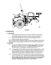
3.4 INSTALL HOPPER ASSEMBLY
44 and 48 inch units (52 inch units skip to step 3.4.5)
Remove the (12) bolts that retain the “HOT” engine guard shield (Item 1). Discard (8) of
the bolts and retain (4). Keep all (12) nuts for reuse in Step 3.4.3.
3.4.1. Working from the front side of the bagger mount, slide the top end of the engine
guard up and into the mount. Pivot the lower end through the bagger mount and
slide it down into place until the holes align with the holes in the bagger mount
(See Figure 7).