


- 32 -
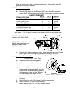
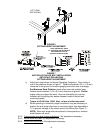
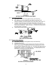
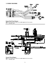
FIGURE 12
MOTION CONTROL LINKAGE ADJUSTMENT
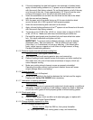
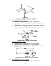
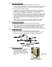
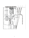
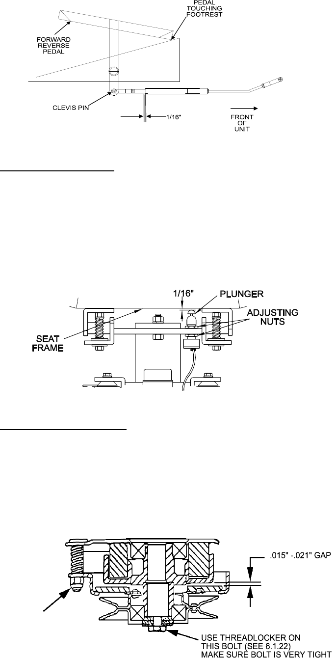
6.2.11 Seat Switch Adjustment
a) Stop engine, wait for all moving parts to stop, and remove key.
b) With operator out of seat, adjust the seat switch to provide a 1/16”
clearance between the switch plunger and the seat frame (See Figure 13).
c) To adjust, loosen the top nut securing the seat switch to the seat rail
weldment. Adjust the bottom nut until the 1/16” between plunger and seat
frame has been obtained. Tighten the top nut. Recheck the measurement
and adjust again if necessary.
d) Check safety interlock system as outlined in 6.1.5.
FIGURE 13
SEAT SWITCH ADJUSTMENT
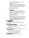
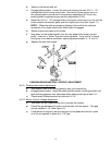
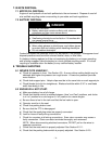
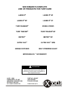
6.2.12 Electric Clutch Adjustment
a) Stop engine, wait for all moving parts to stop, and remove key.
b) Engage parking brake.
c) Place .015-.021 inch feeler gauge through each of the three clutch gap
holes. If gap exceeds this range, tighten the three adjusting nuts (c) until
the proper gap is obtained (See Figure 14). The three clutch gap holes are
located at the “nut side” of the adjusting bolts. The adjusting bolts can be
identified by the springs surrounding each bolt.
FIGURE 14
ELECTRIC CLUTCH ADJUSTMENT
( c )