


- 15 -
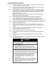
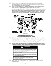
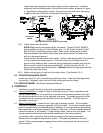
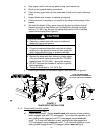
Locate two holes along the back center section of the mower deck. Install the
stationary idler and related parts in the left hand hole location as shown in Figure
3. See the belt routing decal on deck. Be sure the coned end of the disc spring
is against the head of the bolt as illustrated (See Figure 3).
FIGURE 3
IDLER PULLEY KIT AND LOCATION
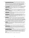
3.8.7 Install mower deck drive belt.
NOTE: Make sure to use proper belt for your deck. The belt (Part #1-543523)
that is installed on the unit is for 60”decks only. For 52” decks, the belt (Part #1-
543749) from the bolt bag must be used. Refer to belt routing decal on deck.
Slip belt between clutch drive sheave and drive wheel release rod (make sure
belt is in the sheave groove).
Install the deck drive belt around the clutch. Refer to belt routing decal. Be sure belt
is in the clutch drive sheave groove. Place the other end of the belt into the V-
groove of the stationary idler, move the spring loaded idler outward and route the
belt around the inside of the spring loaded idler. Position the belt into the V-
groove of the mower deck drive sheave. Carefully release the spring loaded idler.
Install the center belt shield.
3.8.8 Adjust cutting height of deck and anti-scalp rollers. (See Section 6.2.1.)
3.9 POSITION DISCHARGE CHUTE:
Loosen two (2) 5/16” nyloc nuts attaching discharge chute. Lower the discharge chute
into position. Retighten nyloc nuts until chute is snug but can pivot freely.
3.10 SERVICE ENGINE: See Engine Operator's Manual.
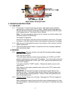
4. CONTROLS
Familiarize yourself with all controls before operating the mower.
4.1 Steering Handle Bar: Located in center of steering console in front of operator’s seat.
During forward operation of the machine, movement of the steering handle to the right
will cause the machine to turn to the right and vice versa. The steering system is chain
connected from the steering shaft sprocket to the yoke sprocket. The chain has two
adjustable connectors.
4.2 Motion Control Pedal: Located on the right side of steering console. The foot pedal
controls the forward and reverse operation with foot motion. To increase forward speed
press front pedal down until desired speed is obtained, to increase reverse speed press
back pedal down until desired speed is obtained. Movement of the front pedal down will
cause the machine to go forward. To stop forward travel, remove foot from pedal. The
neutral centering device moves the motion pedal back to the neutral position.
For reverse motion, place foot heel on the rear pedal pad and press downward.
Remove foot from pedal to stop reverse motion. The pedal automatically returns to
neutral. When parking brake is engaged, the motion control pedal can be moved but
will not function.
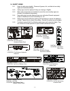
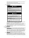
3/8 HEX CAP
SCREW
3/8 WHIZLOCK NUT