


- 14 -
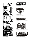
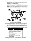
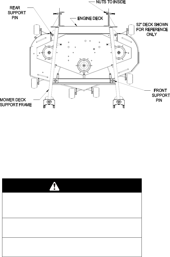
3.8.2 Remove mower deck support frame from mower deck by removing the two
hairpins and spacers from the front deck support pins and remove the hairpins
and spacers from the rear deck support pins.
3.8.3 Lift up on support frame until it clears the support pins. Position support frame
so the arms are on each side of the tractor engine deck and secure.
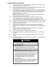
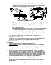
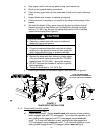
Secure using eight (8) 3/8-16 x 1 1/4” bolts, disc spring washers, and whizlock nuts.
NOTE: Place spring washer cone side against bolt head (cupped side away from
head) and install to outside of support frame (as shown in Figure 2). Install with
whizlock nuts to the inside of engine deck. Tighten until spring washers are flat.
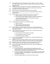
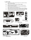
FIGURE 2
HARDWARE AND SUPPORT PIN
LOCATION FOR DECK SUPPORT FRAME
3.8.4 Position tractor, with mower deck support frame in place, over the mower deck.
Align support frame above mower deck and position it so the support pins on the
deck align with the mounting holes in the support frame. Lower support frame onto
deck and Reinstall the two hairpins and spacers on the front support pins and the
two hairpins and spacers onto the rear support pins (See Figure 1).
3.8.5 After the mower deck support frame and the attached mower deck are in place, it
is necessary to remove the two wooden blocks under the engine deck pivot stops.
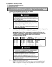
CAUTION
POTENTIAL HAZARD
♦ Removing the two blocks prior to installing the mower
deck and support for counter balance will allow the
engine deck to flip backwards.
WHAT CAN HAPPEN
♦ If the engine flips backwards pinch points are created,
which may cause injury.
HOW TO AVOID THE HAZARD
♦ Keep hands clear from the engine deck when
removing the blocks.
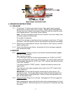
3.8.6 Install mower deck stationary idler. Idler components are located in the Turf
Ranger bolt bag.