


- 24 -
Note: Be sure to check idler on transmission drive belt. Disassemble, clean and
grease pivot bushing if necessary.
6.1.13 Lubricate grease fittings.
a) Stop engine, wait for all moving parts to stop, and remove key.
b) Lubricate fittings with one to two pumps NGLI grade #2 multi-purpose gun
grease. Refer to the following chart for fitting locations and lubrication schedule.
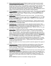
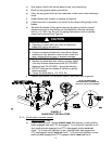
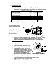
LUBRICATION CHART
FITTING LOCATIONS
INITIAL
PUMPS
NO of
PLACES
SERVICE
INTERVAL
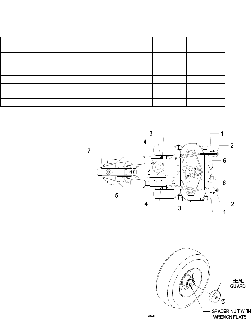
1. Front Caster Wheel hubs w/o zerk *0 2 Yearly
2. Front Caster Pivots *0 2 Yearly
3. Drive Wheel Bearings 1 2 200 hours
4. Engine Deck Pivots 1 2 40 hours
5. Steering Column 1 1 40 hours
6. Idler Pivots, Mower Deck 1 2 40 hours
7. Rear Steering Wheel Bearings 1 1 200 hours
* See 6.1.13 Section c) for special lubrication instructions on the front caster pivots
and Section 6.1.14 for special lubrication instructions on the front caster wheel hubs.
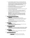
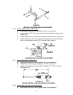
No. 3 (Drive Wheel Bearings)
Located Under Engine Deck
No. 6 (Idler Pivots, Mower Deck)
Monthly disassemble belt and
spring and grease under a
“No Load” condition.
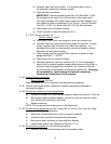
c) Lubricate front caster pivots once a year. Remove hex plug and cap. Thread
grease zerk in hole and pump with grease until it oozes out around top
bearing. Remove grease zerk and thread plug back in Place cap back on.
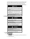
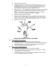
6.1.14 Lubricate caster wheel hubs:
Service Interval: Once Yearly
a) Stop engine, wait for all moving parts to
stop, and remove key.
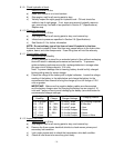
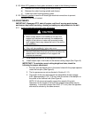
b) Remove caster wheel from caster forks.
c) Remove seal guards from the wheel hub.
d) Remove one of the spacer nuts from the
axle assembly in the caster wheel. Note that
thread locking adhesive has been applied to
lock the spacer nuts to the axle. Remove
the axle (with the other spacer nut still
assembled to it) from the wheel assembly.
e) Pry out seals, and inspect bearings for wear or damage and replace if
necessary.
f) Pack the bearings with a NGLI grade #1 multi-purpose grease.
g) Insert (1) bearing, (1) new seal into the wheel.
NOTE: Seals (Exmark PN 103-0063) must be replaced.
FIGURE 8
CASTER WHEEL ASSEMBLY