


Maintenance
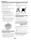
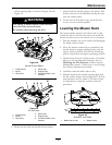
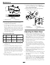
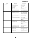
Figure 41
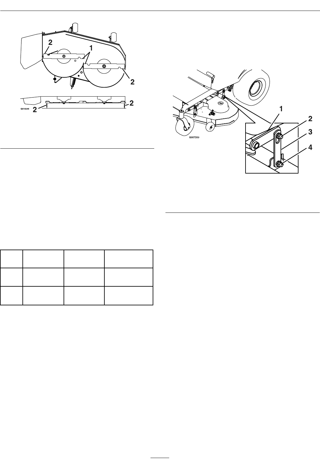
42 Inch Deck
1. Blades side to side 2. Measure here
6. Set anti-scalp rollers to top holes or remove
completely for this adjustment.
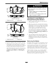
7. Set the height-of-cut lever to the 3 inch (76 mm)
position. Place two “B” thick blocks (see Block
Height and Rake Table) under the rear edge of the
cutting deck skirt; one on each side of the cutting
deck. Place two “A” thick blocks under each side
of the front edge of the deck, but not under the
anti-scalp roller brackets.
Block Height and Rake Table
Deck
Size
Front Block
Height “A”
Rear Block
Height “B”
Rake “R”
42
2.19 inches
(5.6 cm)
2.44 inches
(6.2 cm)
1/8–3/8 inch
(3.2–9.5 mm)
48 &
52
2.31 inches
(5.9 cm)
2.50 inches
(6.4 cm)
1/16–5/16 inch
(1.6–7.9 mm)
8. Carefully rotate the blades side to side (Figure 40
and Figure 41).
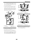
9. Loosen the leveling adjust locking nuts (item 4)
on all four corners so that the deck is sitting
securely on all four blocks. Make sure that the
deck hangers are all the way down (at the top of
the slot) and the deck lift foot lever is pushed back
against the stop, then tighten the four leveling
adjust locking nuts
10. Recheck that blocks t just snugly under the deck
skirt. Make sure all attachment bolts are tight
11. Continue leveling the deck by checking the
front-to-rear blade slope; refer to Adjusting the
Front-to-Rear Blade Slope.
12. Recheck blades for levelness and repeat deck
leveling procedure if necessary.
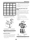
Figure 42
1. Deck lift arm
3. Deck hanger
2. Float retaining nut 4. Leveling adjust locking
nut
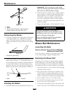
Adjusting the Blade Slope
1. Check the front-to-rear blade level any time you
install the mower. If the front blade tip is not “R”
(see Block Height and Rake Table in Leveling the
Mower Deck) lower than the rear blade tip, adjust
the blade level using the following instructions:
2. Park the machine on a level surface and disengage
the blade control switch.
3. Move the motion control levers outward to
the neutral position, engage the parking brake,
stop the engine, remove the key, and wait for all
moving parts to stop before leaving the operating
position.
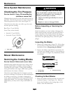
4. Check the air pressure of all four tires. If needed,
adjust to the recommended ination; refer to
Checking the Tire Pressure in Drive System
Maintenance section.
5. Check and adjust the side-to-side blade level if you
have not checked the setting; refer to Leveling
the Mower.
6. Set the height-of-cut lever to the 3 inch (76 mm)
position. Place two “B” thick blocks (see Block
Height and Rake Table in Leveling the Mower
Deck) under the rear edge of the cutting deck
skirt; one on each side of the cutting deck. Place
42