


Maintenance
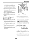
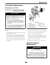
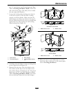
Figure 33
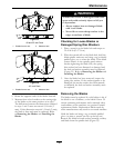
48 and 52 Inch Deck
1. Blades front to rear
2. Measure here
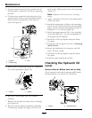
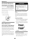
Figure 34
42 Inch Deck
1. Blades front to rear
2. Measure here
2. Rotate the opposite ends of the blades forward.
3. Measure from a level surface to the cutting edge
of the blades at the same position as in step 1.
The difference between the dimensions obtained
in steps 1 and 3 must not exceed 1/8 inch (3
mm). If this dimension exceeds 1/8 inch (3 mm),
the blade is bent and must be replaced. Refer
to Removing the Blades and Installing the
Blades.
WARNING
A blade that is bent or damaged could break
apart and could seriously injure or kill you
or bystanders.
• Always replace bent or damaged blade
with a new blade.
• Never le or create sharp notches in the
edges or surfaces of blade.
Checking for Loose Blades or
Damaged Spring Disc Washers
1. Place a wrench on the blade bolt and torque to
32-42 ft lb (43-57 N-m).
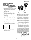
2. With the wrench still on the blade bolt, hold the
blade spindle stationary and using a rag or thickly
padded glove, try to rotate the blade. If the blade
rotates relative to the spindle guard without
further tightening the blade bolt, the spring
disc washer has been attened or damaged and
the bolt and washer assembly must be replaced
(Figure 35). Refer to Removing the Blades and
Installing the Blades.
3. Once the blade has been removed, inspect the
spring disc washer. If the washer appears to be
damaged (the washer surface has been marred)
or attened, the bolt and washer assembly must
be replaced.
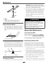
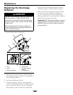
Removing the Blades
The blades must be replaced if a solid object is hit, if
the blade is out of balance, or the blade is bent. To
ensure optimum performance and continued safety
conformance of the machine, use genuine Exmark
replacement blades. Replacement blades made by
other manufacturers may result in an unsafe machine.
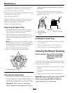
Hold the blade end using a rag or thickly-padded
glove (or place a wrench on the top sheave nut).
Remove the blade bolt and washer assembly, washer,
and blade from the spindle shaft (Figure 35).
39