


Maintenance
Voltage
Reading
Percent
Charge
Maximum
Charger
Settings
Charging
Interval
12.6 or
greater
100%
16 volts/7
amps
No
Charging
Required
12.4 – 12.6 75–100%
16 volts/7
amps
30 Minutes
12.2 – 12.4 50–75%
16 volts/7
amps
1 Hour
12.0–12.2 25–50%
14.4 volts/4
amps
2 Hours
11.7–12.0 0–25%
14.4 volts/4
amps
3 Hours
11.7 or less
0%
14.4 volts/2
amps
6 Hours or
More
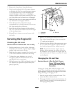
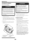
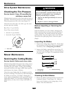
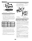
4. When the battery is fully charged, unplug
the charger from the electrical outlet, then
disconnect the charger leads from the battery
posts (Figure 29).
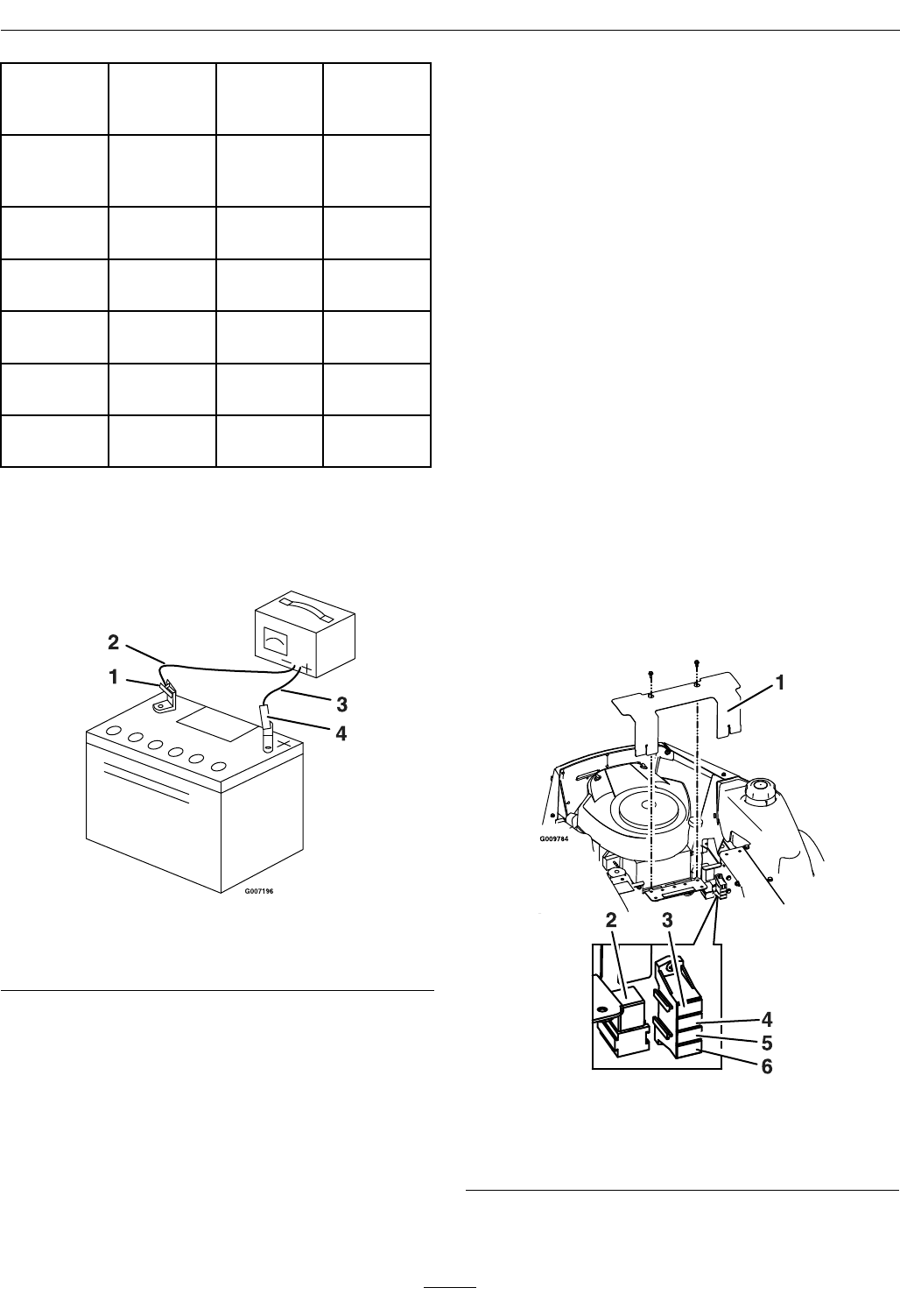
Figure 29
1. Negative battery post
3. Red (+) charger lead
2. Black (-) charger lead
4. Positive battery post
Note: Do Not run the machine with the battery
disconnected, electrical damage may occur.
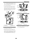
Installing the Battery
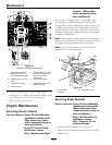
1. Position the battery in the tray with the terminal
posts toward the operating position (Figure 28).
2. Install the positive (red) battery cable to the
positive (+) battery terminal using the fasteners
removed previously.
3. Install the negative battery cable to the negative
(-) battery terminal using the fasteners removed
previously.
4. Slide the red terminal boot onto the positive (red)
battery post.
5. Secure the battery with the strap (Figure 28).
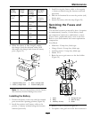
Servicing the Fuses and
Relay
The electrical system is protected by fuses. It requires
no maintenance; however, if a fuse blows, check
the component/circuit for a malfunction or short.
There is also a replaceable relay/s next to the fuse.
Refer to your Parts manual for correct replacement
components.
Fuse Block:
• Main fuse: 25 amp fuse, blade-type
• Charge Circuit: 20 amp fuse, blade-type
• Auxiliary circuit: 15 amp fuse, blade-type
• Diode: TVS
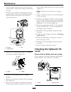
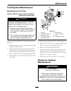
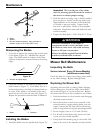
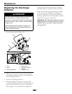
1. Raise the seat to gain access to the fuse holder
(Figure 30).
Figure 30
1. Cover 4. Charge–20 amp
2. Relay 5. Main–25 amp
3. Auxilliary–15 amp 6. Diode
2. Remove cover as shown in Figure 30.
3. To replace a fuse, pull out on the fuse to remove it
37