


DEI PVM-4210
Document Number 9100-0201 Rev 8
Directed Energy, Inc. 2000-2002
Page 7
continuous pulse recurrence frequencies greater than 20KHz. This formula is not
applicable when driving non-capacitive (resistive or inductive) loads. Contact DEI
for information or assistance in using the PVM-4210 with different load
characteristics or impedances.
4.0 Connector Pin-Outs And User Adjustments
Input And Output Connectors:
DB-15 PIN Number Function
P1 - 2 Ground
P1 - 3 +5VDC Output For Enable Circuit (See text
below)
P1 - 6
Gate TTL into 50Ω
P1 - 7 +24VDC Return (Ground)
P1 - 9 Non-inverted gate polarity select (When
jumpered to pin 10)
P1 - 10 Gate/Output polarity select
P1 - 11 Inverted gate polarity select (When jumpered
to pin 10)
P1 - 12 Gate Return (Ground)
P1 - 14 Power Supply Enable Input (TTL High)
P1 - 15 +24VDC to +28VDC
+ Pulse Out: Positive Pulse Output (SHV Connector, End Panel)
- Pulse Out: Negative Pulse Output (SHV Connector, End Panel)
Controls:
+HV Adjust: +V Adjust, Full Counter-Clockwise = 0V
-HV Adjust: -V Adjust, Full Counter-Clockwise = 0V
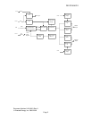
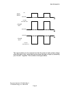
4.1 Polarity Reversal
The output polarity can be easily selected through jumpers on pins 9, 10 and
11 of the DSUB connector.
When pins 9 and 10 are jumpered together, the output is non-inverted. The
output is held at ground when the pulser is not gated (i.e. the TTL gate is low).
When the TTL gate is high, the output of the pulser is connected to the
potential of the high voltage DC power supplies. This is shown in the figure
below: