


DEI PVM-4210
Document Number 9100-0201 Rev 8
Directed Energy, Inc. 2000-2002
Page 9
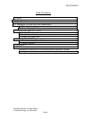
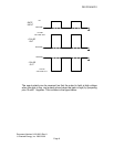
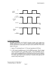
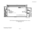
Output Pulse Configuration With Inverted Gate Selected
4.2 Power Supply Enable
For safety and flexibility, the PVM-4210 features a power supply enable input
(DSUB connector pin 14). In order to enable the DC power supplies (and
therefore generate an output pulse), this input must be held HIGH. This can be
done in two ways:
1. Apply a TTL high signal to pin 14. The input impedance is 5K Ohms.
2. A +5V output is available on pin 3 of the DSUB connector. This 5V output
can be connected to pin 14 through a switch. In this configuration, the DC
power supplies can be enabled and disabled by closing the switch between
pins 3 and 14. WARNING: This 5V output should only be used for satisfying
the enable signal requirements of the driver. It should not be used as a 5V
source for any other purpose.
GATE
INPUT
GROUND
+5V
+ PULSE
OUT
GROUND
GROUND
+ PULSE
VOLTAGE OUT
- PULSE
VOLTAGE OUT
- PULSE
OUT