


DEI PVM-4210
Document Number 9100-0201 Rev 8
Directed Energy, Inc. 2000-2002
Page 4
photomultiplier tubes. The exceptional pulse fidelity of the PVM-4210 will
optimize the performance of any system in which it is used.
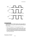
The module provides two pulse output channels, controlled by a common
control logic. When the control logic receives a gate signal, both channels
pulse simultaneously. One channel pulses from ground to the positive high
voltage, and the other channel pulses from ground to the negative high
voltage. Therefore each output can be connected to the electrodes of a
Pockels Cell or Q-Switch, or to a pair of deflection plates, providing a 1,900V
differential pulse across the cell or plates. These outputs may also be
inverted, to pulse from the high voltage potential to ground. The width and
frequency of the output pulses follow the width and frequency of the TTL
input gate. The amplitude of the output pulse voltage for each channel is
independently adjustable from 0 to 950V using screwdriver-adjustable
potentiometers readily accessible on the end panel of the pulser module.
The PVM-4210 requires +24VDC to +28VDC support power and a TTL (into
50Ω) gate signal. For safety and control flexibility, a TTL level signal is
used to enable and disable the DC power supplies. Each channel is a half-
bridge (totem pole) design, offering equally fast pulse rise and fall times,
low power dissipation, and virtually no over-shoot, under-shoot or ringing.
The unit has over-current detection and shut-down circuitry to protect the
pulse generator against potential damage due to arcs and shorts in the load
or interconnect cables.
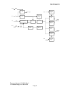
The block diagram below shows the main functional blocks of the pulser: