


DEI PVM-4210
Document Number 9100-0201 Rev 8
Directed Energy, Inc. 2000-2002
Page 10
5.0 OPERATING INSTRUCTIONS
WARNING
1. Do not remove the input or output cables while the pulser is in operation. Never
intentionally short-circuit the high voltage output of the pulser. Failure to observe
these precautions can result in potential electric shock to personnel, arcing, and
damage to the connectors and system.
4. Pulsed power systems are capable of random triggering via transients and
therefore when the pulse generator is turned on, or high voltage is present in the
chassis, assume it is possible to get a pulse on the output connector.
5.1 Output Cabling
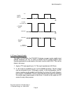
The PVM-4210 is designed to drive capacitive loads with fast rise times.
Since the current out of the PVM-4210 is limited, the lower the
capacitance, the faster the risetime. Given fixed load characteristics, only
the interconnecting cable type and length will vary the output capacitance.
The unit is supplied with 1 foot lengths of RG-59 coaxial cable which has a
capacitance of 21.5pF per foot. The unit is series terminated in the
characteristic impedance of this cable, which is 75Ω. DEI recommends
that the shortest length of cable possible be used to ensure the fastest
possible rise times and best pulse fidelity. Only 75Ω coaxial cable should
be used to connect the output of the pulse generator to the load.
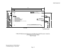
5.2 Load Interconnection
The load should be connected using only 75Ω coaxial cable (RG-59 or
equivalent). Any inductance introduced into the circuit through the use of
wire interconnections, or impedance mismatches caused by using cable
with an impedance other than 75Ω, may causing ringing on the output
pulse, or a general degredation of waveform fidelity. For optimal waveform
fidelity, the ends of the coaxial cable should be connected directly to the
load to minimize interconnection inductance and impedance mismatches.
If it is necessary to use wire leads between the coaxial cable and the load,
the leads should be kept as short as possible. Twisting the leads together
(i.e. using a twisted pair) will reduce the lead inductance and help to
preserve waveform fidelity.
5.3 Power-Up Procedures
The unit should be powered up using the following procedures:
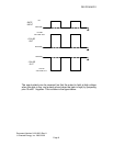
1. Before connecting the input TTL pulse generator to the PVM-4210
pulser, set up the pulse generator output to deliver a TTL level pulse into
50 ohms, with a repetition rate <20KHz, and a pulse width greater than
45ns.