


Technical manual
Page 55 of 72
ST0133 – A 02/09
SOLAR
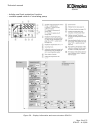
8.2 Pump unit
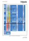
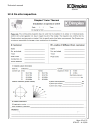
As for the whole system no manual intervention is required on the pump unit when the
system is operating normally. However, the pump unit offers some useful information
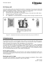
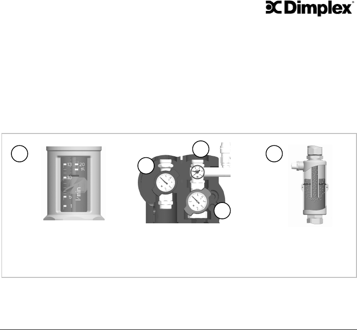
detailing the operational status of the solar system (see Figure 57):
A: current flow rate: to be seen on flow meter
B: flow and return temperature: approximate values on flow and return ball valves
C: operating pressure: pressure gauge
D: air – separation: to be carried out on air purger without having to access the roof
Figure 57 – Operational information provided by Dimplex solar pump unit SOLPU1/2
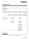
9 Maintenance
The maintenance effort for the Dimplex solar system is minimal and can ideally be exe-
cuted when carrying out the mandatory checks on the unvented hot water installation.
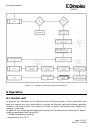
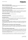
Figure 58 details the schedule of the maintenance to be carried out.
It is recommended to check the function of the system after the 1
st
year of operation
and then carry out a bi-annual maintenance check. Not all steps have to be undertaken
every two years as detailed in Figure 58. All the values measured during the mainte-
nance procedure are to be recorded in the appropriate fields in the maintenance sched-
ule. The following steps are part of the system maintenance:
Check system pressure
The original system pressure can be found on the system commissioning sheet con-
tained in the on site guide. Should the pressure have reduced considerably, the cause is
to be investigated.
Check pipe work for leaks
This step is only required if the system pressure dropped considerably. Where readily
accessible joints should be checked for signs of small leaks.
A:
D:
Note: thermometers shown in
“open” position. During normal
operation the handles are to be
u
p
-ri
g
ht.
C:
B:
B: