


Technical manual
Page 28 of 72
ST0133 – A 02/09
SOLAR
flexible hose SOLFH10/15 is DN16 and only provides ¾” connections. Should this prod-
uct be applied to the SOLPU2 a 1” to ¾” reducer has to be provided with sufficient seal-
ing surface for the flat seal to sit against. The 1”F x 22mm or 1”F x 28mm straight con-
nection has to be provided by the installer.
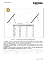
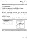
6 bar pressure relief valve (3)
The 6 bar pressure relief valve is part of the safety components in the solar circuit. Its
correct application is therefore important. The discharge pipe from the relief valve must
be:
- 22mm copper pipe
- with no more than 2 bends
- terminating safely (it is recommended to end the discharge pipe in a suitable vessel
and not to discharge to drain)
Should the pressure relief valve open and discharge fluid, this is a clear sign that the
system is malfunctioning. The malfunction can be caused by:
- cold fill pressure of system too high
- expansion vessel too small
- expansion vessel pre-charge not adjusted correctly
- expansion vessel faulty
- solar collector array considerably oversized
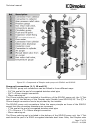
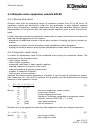
Pressure gauge (4)
The pressure gauge indicates the current pressure inside the solar thermal loop. In a
properly designed, installed, commissioned and operated system the pressure indicated
by the pressure gauge should remain constant in all operating conditions.
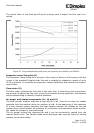
Non return ball valve, temperature gauge (5 and 16)
The non return valve is critical in a solar thermal system to avoid gravity circulation at
times when the cylinder is warmer than the collector as during night time hours. The
non return valves avoid unwanted gravity circulation from the cylinder to the collector,
thus losing energy from the system. As both the flow and the return path of the
SOLPU1/2 pump units have a non return valve the circulation of flow from the collector
to the cylinder can be eliminated when the pump is switched off.
The non return valves have an integrated ball valve which can be closed by turning the
handle with the integrated manual thermometer by 90°. This allows the temporarily
isolation of certain parts of the system for maintenance purposes. The non return valves
can be opened for venting or draining purposes by turning the handles to 45°.
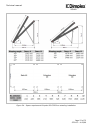
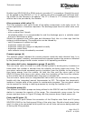
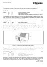
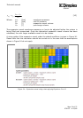
Circulation pump (6)
Two different circulation pumps are being utilised in the SOLPU1 and the SOLPU2 pump
station to increase the capacity of the range. The characteristic pump curves for the
pumps used are shown in Figure 30 along side the pressure drop of each pump unit.
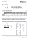
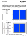
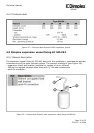
Flush and fill point (7)
The flush and fill point allows the connection of the Dimplex solar flush and fill pump
SOLFFP110/240 for the flushing and filling of the solar loop. Should a hand pump being
used it is also to be connected at this point but not all three valves are being made use
of during the filling process.