


Technical manual
Page 20 of 72
ST0133 – A 02/09
SOLAR
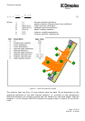
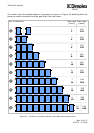
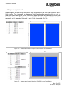
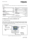
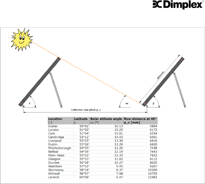
Figure 19 – Free standing kit row distance calculation details
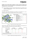
In addition to the row distance the fixation of the free standing kit to the mounting sur-
face has to be considered carefully. Due to the shape of the flat plate collector consid-
erable wind forces can act on the free standing kit installation.
Ideally the free standing kit is bolted to a fixed structure. However, this is not always
practicable, especially when the roof surface must not be penetrated for water tight-
ness reasons.
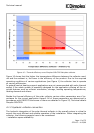
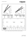
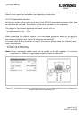
Equation 4 is to be used to calculated the required mass to securely locate the free
standing kit. The required parameters can be found in Figure 20.
Note: the stated parameters are only valid for the wind speeds stated in Figure 20. It is
the responsibility of the installer/mechanical engineer to validate these figures for the
individual installation. Dimplex does not accept any liability for damage to material,
buildings or persons resulting from free standing installations not being sufficiently sup-
ported.