Technical manual
Page 14 of 72
ST0133 – A 02/09
SOLAR
- collector design
- collector pressure drop
- flow rate
- required system output
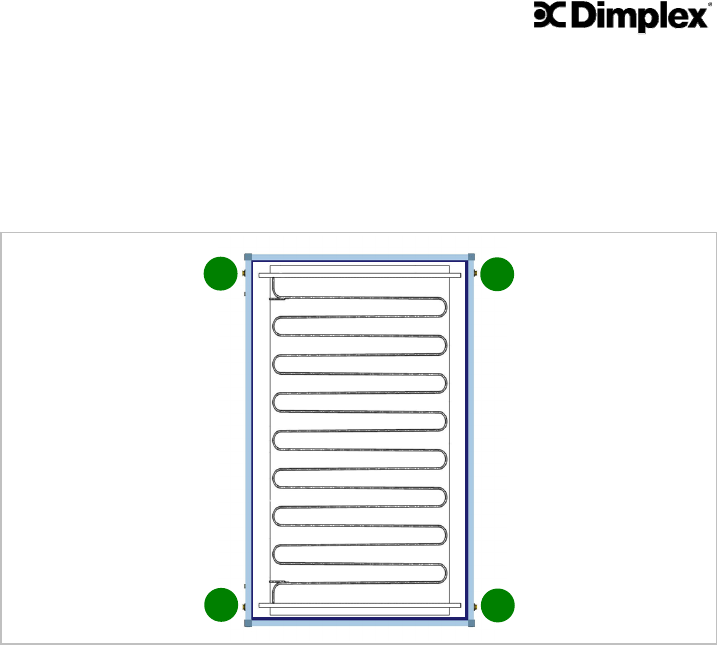
Figure 11 shows the Dimplex SOLC220 collector with the pipe work attached to the ab-
sorber plate indicated.
Figure 11 – Absorber pipe work Dimplex SOLC220 collector
From Figure 11 it can be seen that the collector has 4 connections which can be used to
connect the flow and return pipes of the installation and to connect the collectors be-
tween each other. The 4 connections offer the following features:
- one collector for small or large installations
- left hand or right hand side connection of single collector installations
- up to 10 collectors directly connected together
- collectors connected in parallel to each other, thus low overall pressure drop of array
- same collector for vertical or horizontal installations
The sensor pockets to connect the collector sensor T1 from the control unit are always
on the side with the connections marked (A) and (C). It is important to ensure that all
of the pipe work within the collector is being utilised:
- for single collector installations, the flow and return pipes must be installed on con-
nections (B) and (D).
- for multiple collector installations the sensor pockets must always face outwards.
C
D
A
B


