


108319-01B
7
7
For more information, visit www.desatech.com
For more information, visit www.desatech.com
V
a
r
i
a
b
l
e
F
a
n
S
w
i
t
c
h
W
h
i
t
e
W
h
i
t
e
B
l
a
c
k
G
r
e
e
n
O
n
1
1
0
/
1
1
5
V
.
A
.
C
.
B
l
o
w
e
r
M
o
t
o
r
B
l
a
c
k
B
l
a
c
k
B
l
a
c
k
O
f
f
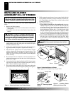
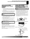
6. Place the blower against lower rear wall of firebox outer wrap-
per with the exhaust port directed upward. Align the holes in
top mounting tabs of blower with holes in wall of wrapper
(see Figure 18, page 6). Using 2 screws provided, mount blower
and tighten screws securely.
7. Be certain that all wire terminals are securely attached to ter-
minals on blower motor and that the screw retaining the green
ground wire is tight.
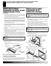
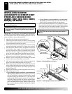
8. Place control knob provided on plastic control shaft of
speed control.
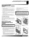
9. Mount the speed control on the front leg of the left floor support
bracket using 2 screws provided (see Figure 19).
Note:
Some
remote ready fireplace models have the gas control located near
the left floor support bracket. For these models, mount the blower
speed control onto the right floor support bracket.
10. Plug in blower power cord.
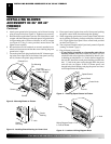
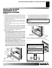
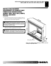
a. If your fireplace system is installed as a freestanding unit
with an accessory mantel, determine whether the power cord
will exit the left side or the right side of the firebox. Install 1
plastic bushing provided into the 1.5" hole in the floor support
bracket on the exit side (see Figure 20). Install the second plas-
tic bushing provided into the 1.5" hole in the outer casing through
which the power cord will exit. Route power cord through both
plastic bushings and plug the power cord into a properly
grounded 3-prong wall receptacle near the firebox.
b.If your fireplace system installation is recessed and if an
outlet is not installed in your fireplace, you must install the
GA3555 Outlet kit with cover in your fireplace which will sup-
ply a convenient 3-prong grounded electrical outlet for your
blower. Refer to the installation manual provided with the model
GA3555 accessory for instructions on wiring the duplex outlet.
Note:
A qualified installer must make all electrical connections.
CAUTION: Never touch the blower wheel while in
operation.
Figure 19 - Attaching Speed Control to Firebox
Screws
Speed Control
Control
Knob
Left Floor
Support
Bracket
Control
Shaft
INSTALLING BLOWER
ACCESSORY IN 32"
FIREPLACE SYSTEMS
Continued
Figure 20 - Installing Plastic Bushing for Power Cord
Plastic
Bushing
Right Floor
Support Bracket
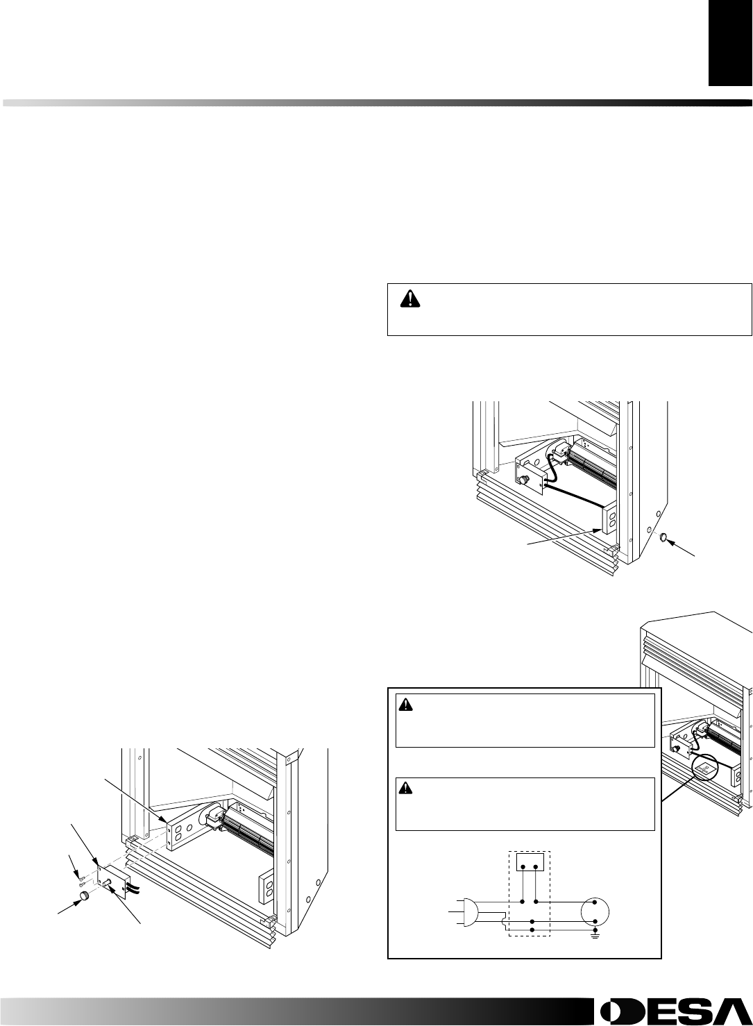
11. Check to make sure that the power cord is completely clear of the
blower wheel and that there are no other foreign objects in blower
wheel. Turn blower on and check for operation. Turn blower off
by rotating knob fully counterclockwise before continuing.
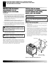
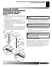
12. Peel off the backing paper and stick the supplied wiring diagram
decal on the firebox bottom approximately 3" to the right of the
blower speed control (Figure 21).
Figure 21 - Location of Wiring Diagram Decal 3" from Blower
Wiring
Diagram
101584-05
120 Vac. 60 Hz. . 78 Amps
DESA, Bowling Green, KY
Variable
Fan Switch
WhiteWhite
Black
Green
On
110/115
V.A.C.
Blower
Motor
Black
Black
Black
Off
WARNING: Never attempt to service heater while it
is plugged in, operating, or hot. Burns and electrical
shock could result. Only a qualified service person
should service or repair heater.
If any of the original wire as supplied with the appliance must be
replaced, it must be replaced with 105°C wire or it’s equivalent.
WARNING: Label all wires prior to disconnection
when servicing controls. Wiring errors can cause im-
proper and dangerous operation. Verify proper opera-
tion after servicing.
INSTALLING BLOWER ACCESSORY IN 32" FIREPLACE SYSTEMS