


108319-01B
5
5
For more information, visit www.desatech.com
For more information, visit www.desatech.com
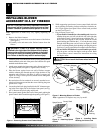
CAUTION: Never touch the blower wheel while in
operation.
b.If your firebox installation is recessed and/or pre-wired,
plug the power cord into the duplex outlet provided. Refer
to your firebox owner’s manual for instructions on wiring
the duplex outlet.
12. Check to make sure that the power cord is completely clear of the
blower wheel and that there are no other foreign objects in blower
wheel. Turn blower on and check for operation. Turn blower off
by turning knob fully counter-clockwise before continuing.
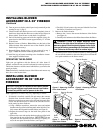
13. Peel off the backing paper and stick the supplied wiring dia-
gram decal on the firebox bottom approximately 12" in front
of the blower (see Figure 12, page 4).
14. Replace and reattach firebox bottom using 4 screws removed
in step 2 (see Figure 8, page 3).
15. If previously removed, carefully replace the firebrick side pan-
els and/or floor in the firebox (see Figures 5-7, page 3).
16. Install the log set heater according to the installation instruc-
tions supplied with the heater.
INSTALLING BLOWER
ACCESSORY IN 36" OR 42"
FIREBOX
Continued
WARNING: A qualified service person must install
heater. Follow all local codes.
Note:
Discard the remaining hardware items.
OPERATING THE BLOWER
Light your gas appliance with the blower off. After about 15
minutes, turn the blower on to deliver heated air at the top louvers.
The blower features a variable control which allows you to select the
speed you desire.
Note:
Periodically check the louvers of the firebox and remove any
dust, dirt, or other obstructions.
INSTALLING BLOWER
ACCESSORY IN MODEL SVFBC
FREESTANDING STOVE
NOTICE: Shut off gas heater during the following blower
installation.
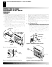
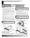
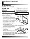
1. Remove the 2 screws and blower mounting bracket from the
rear bottom of the stove cabinet (see Figure 13).
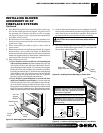
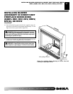
2. Locate the plug button installed in the 10 mm diameter open-
ing in the front of the lower right side panel of the stove cabi-
net (see Figure 14). Remove the plug button and discard.
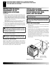
3. Place speed control against inner wall of the pedestal, pushing
the plastic control shaft through the opening.
4. While supporting speed control, secure control shaft with lock
nut by pushing and turning lock nut with pliers clockwise un-
til it is tight against side panel. Place control knob provided on
shaft (see Figure 15).
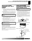
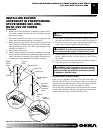
Variable
Fan Switch
WhiteWhite
Black
Green
On
110/115
V.A.C.
Blower
Motor
Black
Black
Black
Off
Figure 13 - Location of Blower Mounting Bracket and Screws
Figure 14 - Location of Plug Button
Screws
Blower
Mounting
Bracket
Wiring Diagram
Plug Button
Speed Control
Lock Nut
Control Shaft
Figure 15 - Attaching Speed Control
Control Knob
INSTALLING BLOWER ACCESSORY IN 36" OR 42" FIREBOX
INSTALLING BLOWER ACCESSORY IN MODEL SVFBC FREESTANDING STOVE