


108319-01B
4
For more information, visit www.desatech.com
For more information, visit www.desatech.com
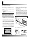
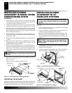
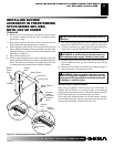
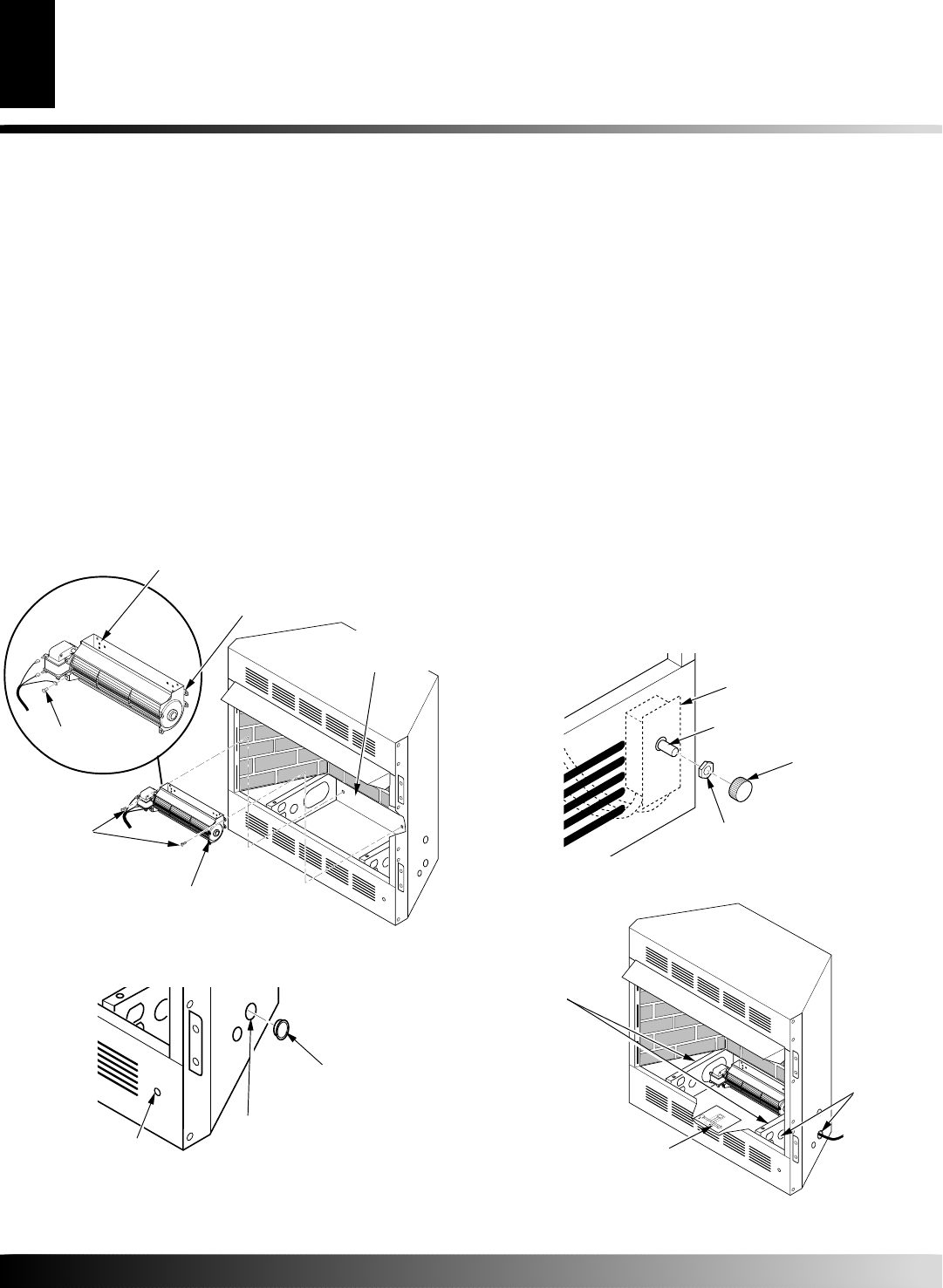
4. Attach green ground wire from power cord to blower housing
using screw provided (see Figure 9). Tighten screws securely.
5. Place the blower against the lower rear wall of the firebox outer
wrapper with the exhaust port directed upward. Align the holes
in top mounting tabs of blower with holes in wall of wrapper
(see Figure 9). Using 2 screws provided, mount blower and
tighten screws securely.
6. Be certain that all wire terminals are securely attached to ter-
minals on blower motor and that the screw retaining the green
ground wire is tight.
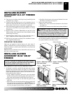
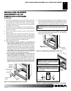
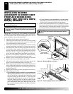
7. Locate the plastic hole plug installed in the 3/8" diameter open-
ing in the lower right side of the firebox front panel (see Fig-
ure 10). Remove the plastic plug and discard.
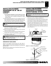
INSTALLING BLOWER
ACCESSORY IN 36" OR 42"
FIREBOX
Continued
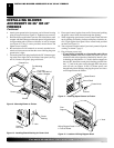
8. Place speed control against inner wall of front panel, pushing
the plastic control shaft forward through the opening.
9. While supporting speed control, secure control shaft with lock
nut by pushing and turning lock nut with pliers clockwise un-
til it is tight against front panel. Place control knob provided
on shaft (see Figure 11).
10. Turn on power to duplex outlet if previously turned off per the
warning in column 2, page 3.
11. Plug in blower power cord.
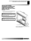
a. If your firebox is installed as a freestanding unit with an
accessory mantel, determine whether the power cord will
exit the left side or the right side of the firebox. Install 1 plas-
tic bushing provided into the 1
1
/2" hole in the floor support on
the exit side. Install the second plastic bushing provided into
the 1
1
/2" hole in the outer casing through which the power
cord will exit (see Figures 10 and 12). Route power cord
through both plastic bushings and plug the power cord into a
wall receptacle near the firebox.
Figure 9 - Mounting Blower to Firebox
Blower
Screws
Top Mounting
Tab
Exhaust Port
Lower Rear Wall of
Firebox Wrapper
Screw
Figure 10 - Installing Plastic Bushing for Power Cord
1
1
/2" Hole
Plastic
Bushing
Plastic
Hole Plug
Figure 11 - Attaching Speed Control to Firebox
Speed Control
Control Shaft
Locknut
Control Knob
V
a
r
i
a
b
l
e
F
a
n
S
w
i
t
c
h
W
h
i
t
e
W
h
i
t
e
B
l
a
c
k
G
r
e
e
n
O
n
1
1
0
/
1
1
5
V
.
A
.
C
.
B
l
o
w
e
r
M
o
t
o
r
B
l
a
c
k
B
l
a
c
k
B
l
a
c
k
O
f
f
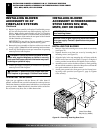
Figure 12 - Location of Wiring Diagram Decal
Wiring Diagram Decal 12"
in Front of Blower
Floor
Supports
1
1
/2" Hole
INSTALLING BLOWER ACCESSORY IN 36" OR 42" FIREBOX