


25
CROSS-CUTTING
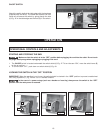
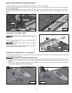
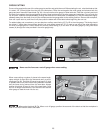
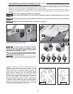
Cross-cutting requires the use of the miter gauge to posi tion and guide the work. Before starting the cut, raise the blade so that
it is about 1/8” (3.2mm) higher than the top of the workpiece. Place the work against the miter gauge and advance both the
gauge and work toward the saw blade (Fig. 64). You can use the miter gauge in either table slot. Start the cut slowly and hold
the work firmly against the miter gauge and the table. Keep both hands on the miter gauge and workpiece. Do not touch the
cut-off piece. Feed the workpiece steadily through the blade until the workpiece is completely cut. Shift the workpiece slightly
sideways away from the blade, then pull the workpiece and miter gauge back to the starting position. Remove the workpiece,
then use a push stick to push the cut-off piece past the blade and off the table before beginning the next cut.
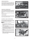
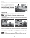
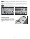
For added safety and convenience, you can attach an auxiliary wood-facing (C) Fig. 65 to the miter gauge. This facing should
be at least 1" higher than the maximum depth of cut, and should extend out 12" or more to one side or the other depending
on which miter gauge slot is used. Attach this auxiliary wood-facing (C) to the front of the miter gauge by using two wood
screws (A) through the holes provided in the miter gauge body.
C
A
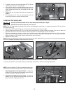
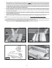
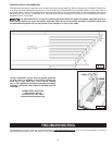
When cross-cutting a number of pieces to the same length,
clamp a block of wood (B) to the fence and use it as a cut-
off gauge (Fig. 66). The block (B) must be at least 3/4" thick
to prevent the cut-off piece from binding between the blade
and the fence during removal from the saw table. Always
position this block of wood in front of the saw blade. Once
the cut-off length is determined, lock the fence and use the
miter gauge to feed the work into the cut.
Never use the fence as a cut-off gauge when cross-cutting.
When using the block (B) Fig. 66 as a cut-off gauge, position the rear end of the block so that the workpiece is
clear of the block before it enters the blade.
Fig. 64
Fig. 65
C
Fig. 66