


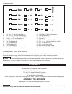
MOBILE BASE AND STAND ASSEMBLY
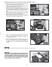
FRONT AND SIDE PANELS
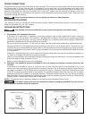
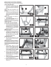
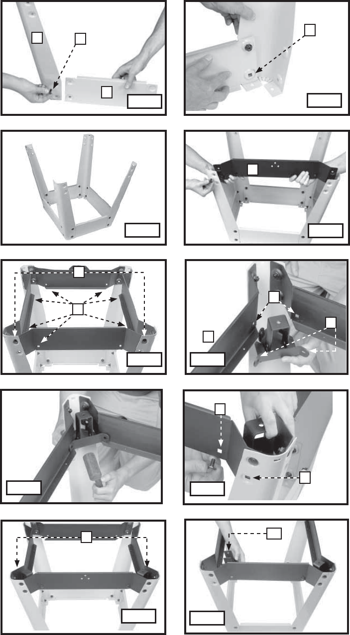
1. Insert a 5/16 -18 x 5/8" carriage head
bolt (A) Fig. 1 through the leg (B) and
the corresponding hole in the panel (C)
Fig. 1.
NOTE: Make sure the squares of the
bolt align with the flat sides of the hole
opening.
2. Thread a 5/16 -18 serrated hex nut (D)
Fig. 2 on the screw. Finger tighten the
panel to the leg. Make sure that the
serrated face of the hex nut is against
the panel.
NOTE: Loosely tighten the hardware for
further adjustment.
3. Fig. 3 shows all four legs attached to
the front and side panels.
NOTE: Make sure that the short panels are
opposite short panels and long panels are
opposite long panels.
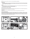
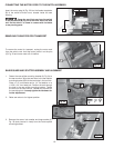
SHORT AND LONG LEG SUPPORTS
4. Attach the long side leg supports (E)
Fig. 4 and the short side leg supports to
the legs using 5/16 -18 x 5/8" carriage
head bolts and 5/16 -18 serrated hex
nuts. Insert the bolt through the leg first
and then the support.
NOTE: Be sure the holes (J) Fig. 5 in all side
supports are aligned.
5. Thread the hex nut on the bolt and
finger tighten only. Attach eight screws
and eight nuts in the holes - two of
which are shown at (F) Fig. 5. Make
sure these holes are on the bottom
(after saw is turned upright).
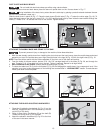
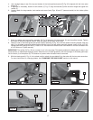
CORNER BRACKETS
6. Align the corner bracket (G) Fig. 6 that
has the closed end with the holes (I) in
the leg supports.
NOTE: Attach the closed-end brackets to
the long leg support that has the 3 holes in
the middle (Fig. 9). If necessary, use a soft
hammer (or a regular hammer and block of
wood) to tap the corner bracket to align the
holes (Fig. 7).
7. Once aligned, attach the corner
bracket to the leg supports using the
5/16 -18 x 5/8" carriage head bolts
and 5/16 -18 serrated hex nuts. Insert
the bolt through the support and the
corner bracket at (K) Fig. 8. Thread a
hex nut on the screw and tighten.
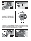
8. Attach the leg to the corner bracket
using the longer 5/16 -18 x 3/4" carriage
head bolts and 5/16-18 serrated hex
nuts in the two holes, one of which is
shown at (L) Fig. 8.
9. Repeat for the other corner bracket.
You will install the rubber leveling feet
on these brackets (G) Fig. 12.
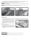
10. Attach the brackets with the open end
(M) Fig. 10 the same as described in
Steps 6 to 9.
Fig. 1
G
11
B
C
A
D
E
J
F
I
H
L
K
G
M
Fig. 2
Fig. 3
Fig. 4
Fig. 5
Fig. 6
Fig. 7
Fig. 8
Fig. 9
Fig. 10
Put the stand together upside down for easier assembly.