


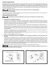
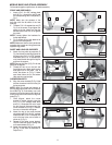
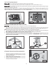
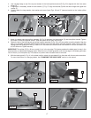
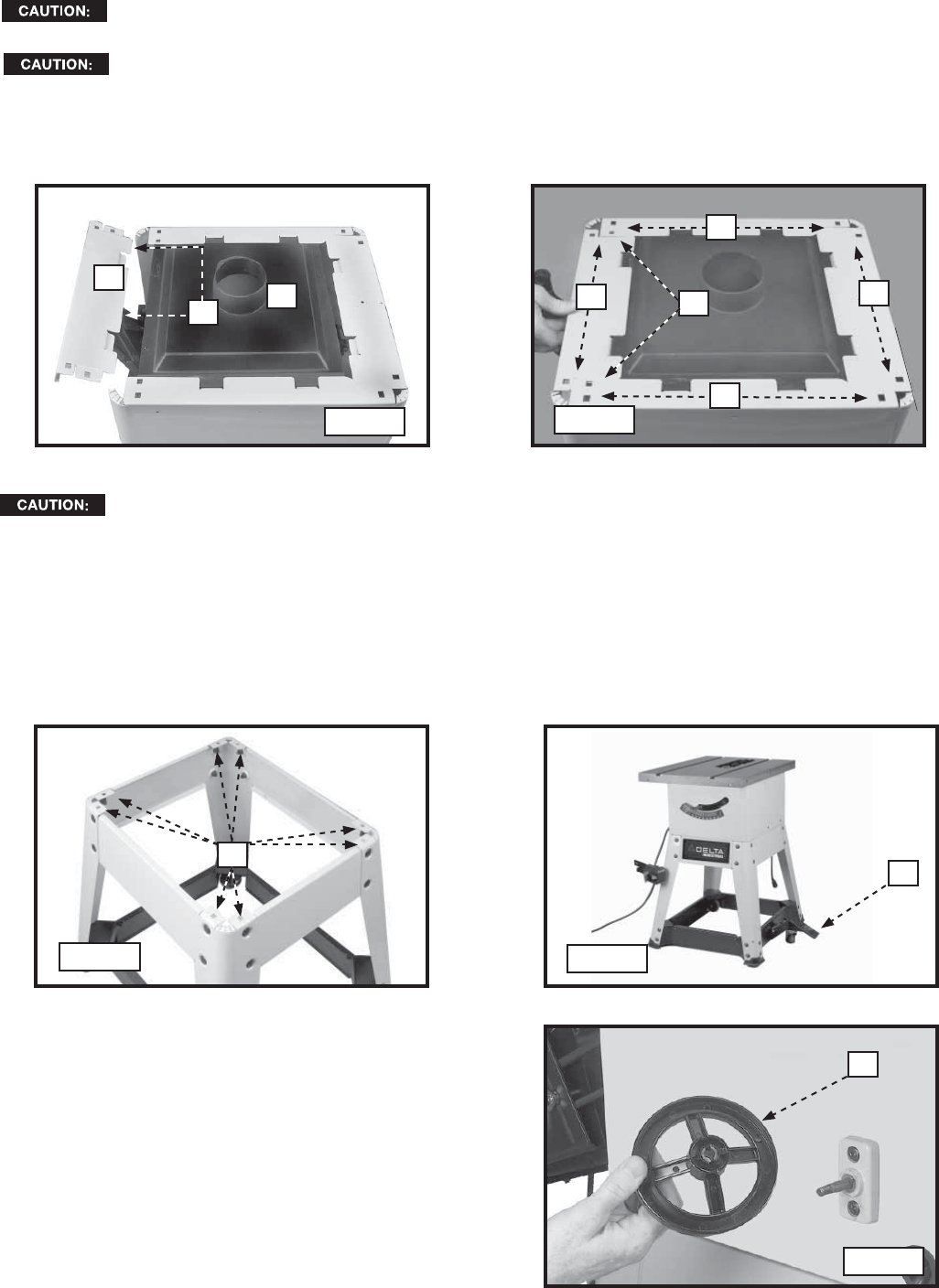
To install the dust chute and back brace, place the saw unit upside down on the floor as shown in Fig. 17.
During installation of the dust chute, protect the saw's table top by placing a protective barrier between the saw
and the floor (cardboard, carpet, etc.).
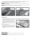
Slide the dust chute in place (A) Fig. 17. Place the back brace (B) with tabs (C) Fig. 17 below the chute edge (Fig. 18). To
fasten the back brace to the saw unit, place 5/16 - 18 x 5/8" carriage head bolts up from inside the saw cabinet through the
holes (E). Thread 5/16 - 18 serrated hex nuts on the screws. Tighten securely.
13
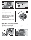
ATTACHING THE MOBILE BASE AND STAND TO THE SAW
To prevent personal injury or damage to the machine, follow these directions:
1. With the saw already upside down from installing the dust chute and the back brace, place the mobile base and stand
assembly on top of the upside-down saw. Align the eight holes in the legs (A) Fig. 19) with the eight holes (D) Fig. 18.
NOTE: Place the shorter panel with the Delta nameplate on the front next to the scale and pointer.
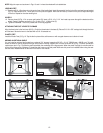
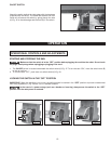
2. From the inside of the saw cabinet, place a 5/16 -18 x 5/8" carriage head bolt in the holes (D) Fig. 26, and through the
legs. Thread a 5/16 -18 serrated hex nut on the bolt. Tighten it securely. Repeat for all eight holes.
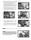
With a minimum of two people, carefully stand the saw upright (Fig. 20).
4. To check the table level, lift up on the foot pedal (C) Fig. 20 to disengage the mobile base. Use a carpenter's level. If the
machine is not level, make adjustments to the leveling feet as described in “LEVELING FEET” section. To make the saw
mobile, push down on the foot pedal.
DUST CHUTE AND BACK BRACE
Do not install this dust chute unless you will be using a dust collector.
Fig. 17
A
B
C
D
D
E
D
D
Fig. 18
A
C
Fig. 19
Fig. 20
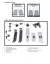
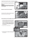
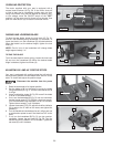
ATTACHING THE BLADE-ADJUSTING HANDWHEELS
1. Place the tilt-adjusting handwheel (A) Fig. 21 on the
shaft (B). Engage the slot in the handwheel (C) with the
roll pin (D) on the shaft.
2. Place a 10mm Nylon Flat Washer (E) on the shaft (B).
Thread the locking knob (F) on the shaft.
3. Attach the elevation handwheel (G) Fig. 22 to the front
of the saw in the same manner.
Fig. 21
A
3.