


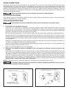
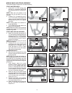
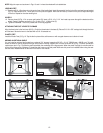
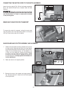
NOTE: Align the open end as shown in Figs. 10 and 11 where the wheels will be installed later.
LEVELING FEET
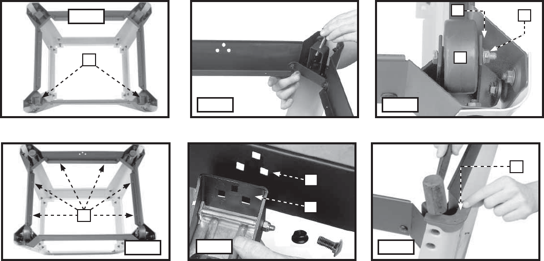
11. Thread one 5/16 -18 hex jam nut on the post of one of the leveling feet. Insert this assembly into the hole of the enclosed corner bracket
(Fig. 12). Place another 5/16 -18 hex jam nut on the post and tighten. Move the hex nuts up or down on the post to adjust the height
of the foot. Repeat for the other leveling foot.
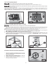
WHEELS
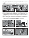
12. Place a wheel (N) Fig. 13 in an open-end bracket (O). Insert a 5/16 -18 x 2-1/4” hex head cap screw through the bracket and the
wheel. Fasten it together as shown in Fig. 13 with a 5/16 - 18 Nylok Nut (P).
13. Tighten all hardware - first on the panels, then on the leg supports.
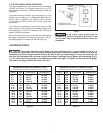
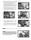
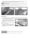
ATTACHING THE FOOT LEVER TO THE BASE
Align the three holes in the foot lever (W) Fig. 15 with the three holes in the base (X). Place a 5/16-18 x 5/8" carriage bolt through the lever
and the base. Secure the lever to the base with a 5/16-18 serrated nut.
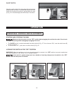
PLASTIC FEET
Install the Plastic Feet (Y) Fig. 16. Tap the feet in place with a soft hammer or with a regular hammer and a block of wood.
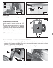
ADDING AN OPTIONAL SHELF
You can install an optional shelf made from a piece of 3/4" plywood measuring 22-3/8” x 19-1/4” (568.96 mm x 488.95 mm). To install,
screw the wood to the leg supports through the (8) holes in the leg supports, six of which are shown at (Q) Fig. 14. When the stand is
upside down (as in Fig. 14), place the shelf underneath the overhangs of the leg supports. When the stand is upright, the shelf would be
on top of the leg support overhangs. To install the shelf, remove one side panel. Make sure this panel is re-installed before using the saw.
See the exact measurements for this shelf in the back of this manual.
12
Fig. 11
Fig. 12
Fig. 13
Fig. 14
Fig. 15
Fig. 16
M
N
O
P
Q
X
W
Y