


Assembly & Set-Up
3
9
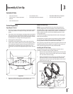
Contents of Crate
Manual
Tractor Preparation
Unpacking the Tractor
Remove the upper crating material from the shipping pallet,
and cut any bands or tie straps securing the tractor to the
pallet.
If the deck is not in the highest mowing position (pushed all 2.
the way forward), use the deck lift pedal to raise the deck to
for instructions on raising and lowering the deck.
Disengage the parking brake.
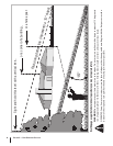
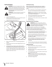
Engage the transmission bypass rods on each side of the 4.
tractor; then carefully roll the tractor off the shipping pallet.
transmission) are located on the rear of the tractor, just
Remove the deck wash system nozzle adapter and oil drain 5.
tube from the manual bag and store for future use.
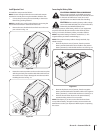
Initial LPG Tank Fill-Up
NOTE: The vapor withdrawal service valve of the Aluminum
threaded safety coupler. Typical forklift cylinders withdraw liquid
propane and have right-handed safety couplers. The different
safety couplers prevent users from installing cylinders on the
wrong equipment.
before the initial fill-up.
It is important to properly purge new propane cylinders before
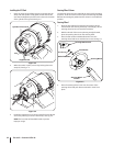
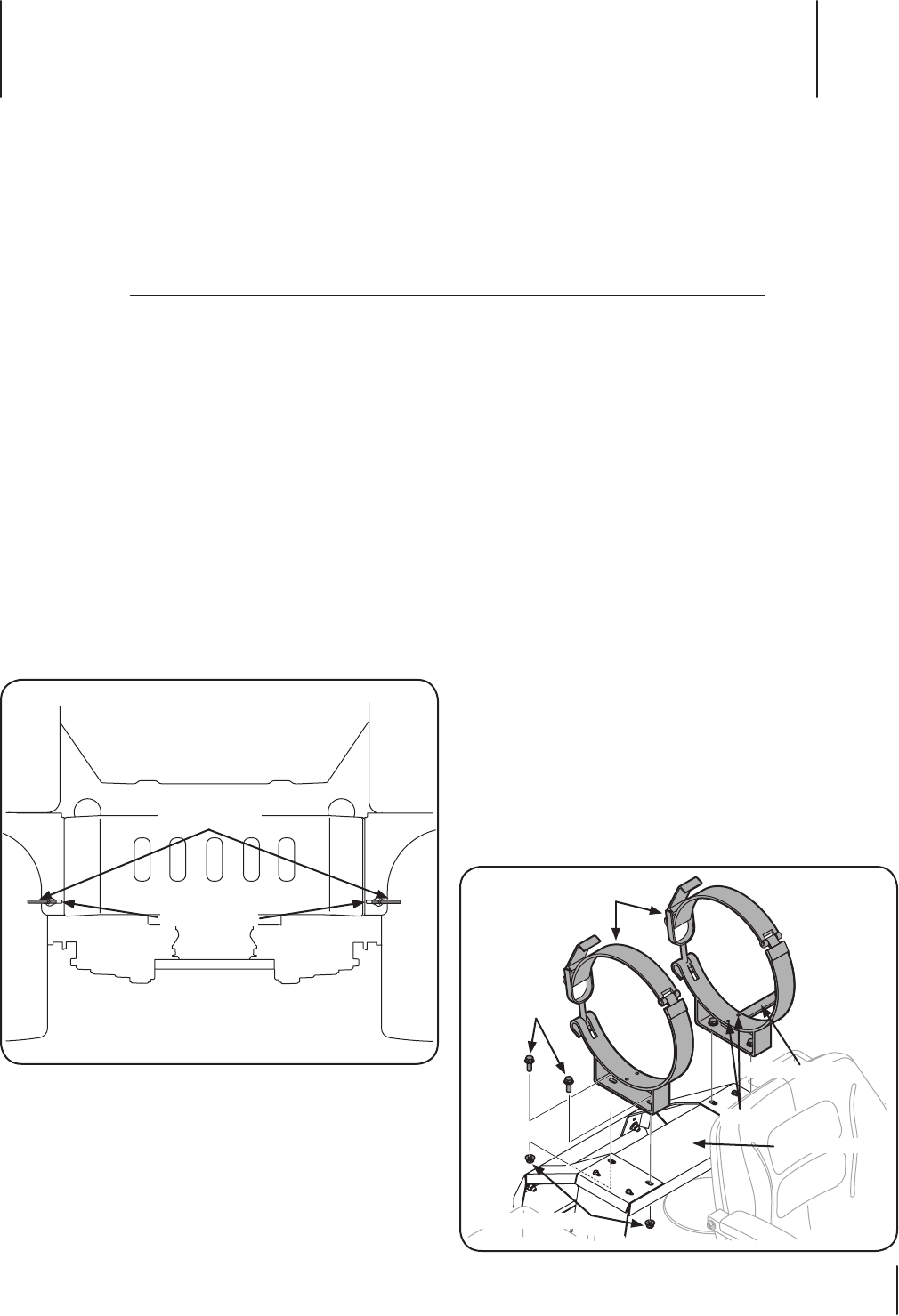
Installing the LPG Tank Straps
The tank straps need to be installed before the tank can be
installed. To install the tank proceed as follows:
Remove the strap assemblies, alignment pin and two bolts
from the box. Then remove the four hex screws and flange
lock nuts from the manual bag.
Mount the alignment pin to the strap assembly using the 2.
flange lock nuts mount the strap assemblies to the mount
Keyhole Slot
Transmission
Bypass Rods
Figure 3-1
Strap Assemblies
Hex Screws
Flange Lock Nuts
Mount Plate
Alignment Pin
Bolts
Figure 3-2