


8
SECTION II. INSTALLATION AND REMOVAL OF MOWER DECK
A. INSTALLATION OF DECK
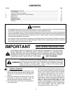
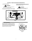
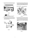
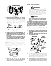
After locking the left lift link as described in Section I ,
start the tractor and use the hydraulic lift to fully raise the
left lift link (See Figure 5). Stop the engine.
Figure 5
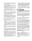
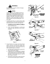
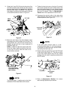
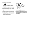
Adjust the mower deck to its lowest setting as follows:
1. Remove the hex flange lock nut from the shoulder
screw securing the gauge wheel to the deck index
bracket. See Figure 6.
2. Insert the shoulder screw w/gauge wheel into the
highest of the four index holes (lowest deck
setting) and secure with the hex flange lock nut.
See Figure 6.
3. Repeat the previous two steps to re-position the
remaining three gauge wheels.
Figure 6
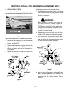
Install the mower deck on the tractor as follows:
1. Place the tractor and mower deck on a firm and
level surface. Position the mower deck on the left
side of the tractor with the front of the deck toward
the front of the tractor.
WARNING
Before installing the mower deck, place the
PTO switch in the “OFF” position, engage the
parking brake lever, and turn ignition key to the
“OFF” position. ALWAYS stop the engine after
utilizing the tractor hydraulic lift system. When
handling the mower deck, be careful not to cut
yourself on the sharp blades.
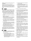
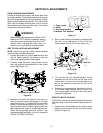
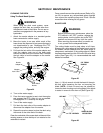
2. Slide the deck under the tractor until the slots of
the LH and RH rear deck brackets align approxi-
mately with the tractor lift links. Refer to Figure 7.
3. Pull outward and cock the deck support pins in
the rear deck brackets so that both spring-loaded
pins are held in the disengaged position against
the inner surface of the deck brackets.
Figure 7
4. Use the tractor lift system to lower the lift links.
NOTE: If installing the deck on a tractor with the
deck downstop feature, make certain the
downstop is in the lowered position (Refer to
Section 1).
LEFT LIFT LINK
FULLY RAISED
INDEX
BRACKET
HEX FLANGE
LOCK NUT
HEX FLANGE
LOCK NUT
GAUGE
WHEEL
SHOULDER
SCREW
SLOT
REAR DECK
BRACKET
PIN LOCKED IN
DISENGAGED
POSITION
DECK
SUPPORT
PIN