


16
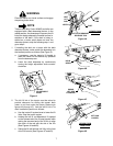
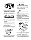
When reinstalling the blades, be sure they are installed
so that the wind wings are pointing upward toward the
top of the deck. Tighten the nuts to 90 to 110 ft-lbs. (122
to 149 N·m).
After replacing the blades, apply grease to the exposed
threads at the bottom of the spindles to prevent rust
buildup.
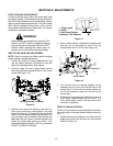
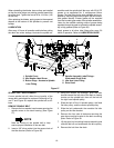
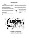
LUBRICATION
After every 10 hours of operation and/or before putting
the deck into winter storage, lubricate the spindle as-
semblies and the spindle belt idler arm with 251H EP
grease or an equivalent No. 2 multipurpose lithium
grease. The lube fitting for the outer spindles can be ac-
cessed by removing the button plugs in the belt covers.
Use grease liberally. Excess grease will be expelled
from the inverted upper seals of the spindle assemblies.
Listen for the muffled crackling noise of grease being
expelled through the seal to indicate the spindle assem-
bly is fully greased (Refer to Figure 29).
Apply grease to all other lube fittings after every 50
hours of operation. Refer to LUBRICATION GUIDE.
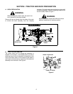
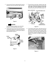
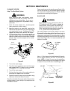
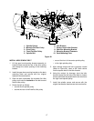
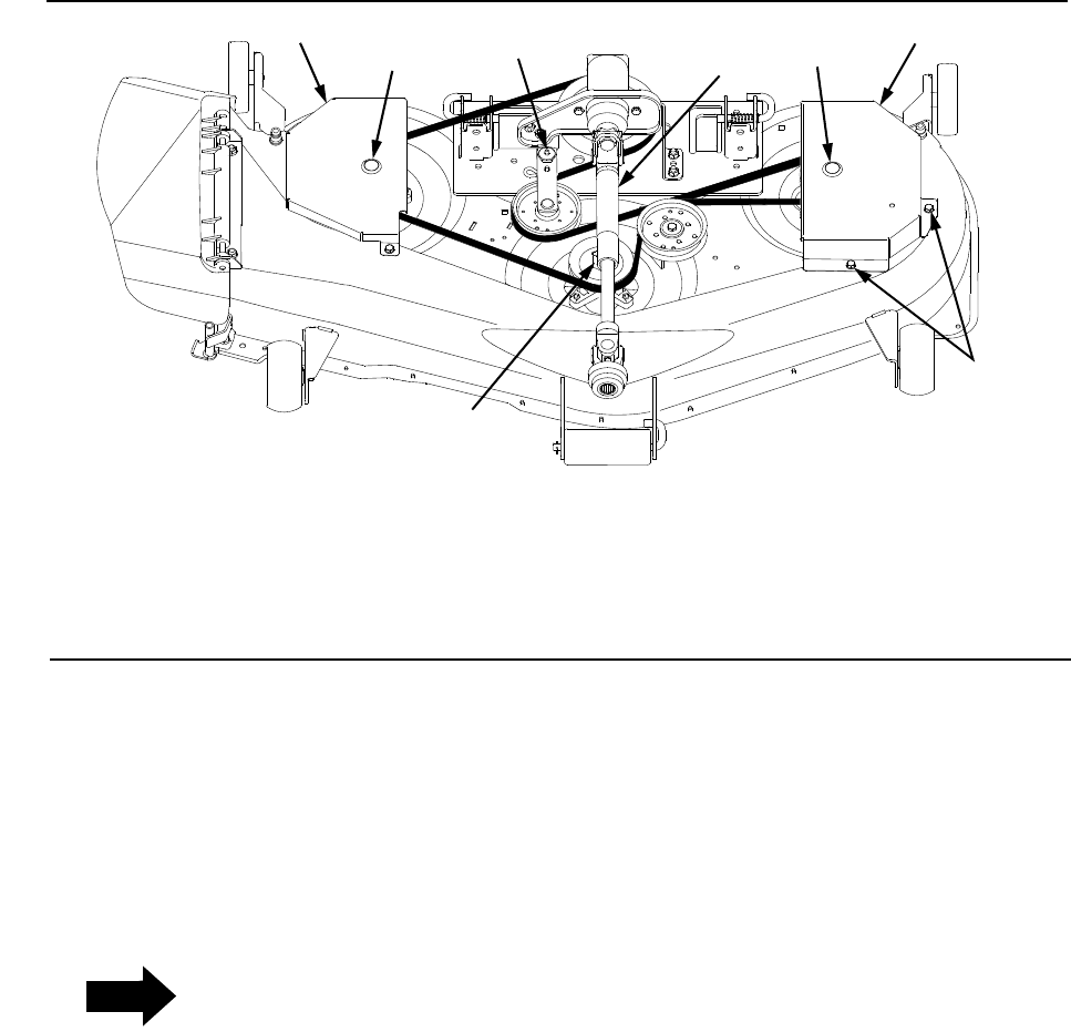
Figure 27
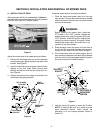
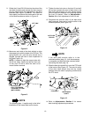
SPINDLE BELT REPLACEMENT
A worn spindle belt will affect the cut quality of the
mower deck and should be replaced. Referring to Fig-
ure 27 and Figure 28, replace the spindle belt as fol-
lows:
REMOVE SPINDLE BELT
1. Remove the hex washer head screws securing the
spindle covers to the deck housing. (See Figure
27).
NOTE
Note the routing of the spindle belt to help
ensure proper installation of the new belt.
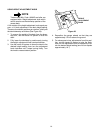
2. Insert a 3/8” drive ratchet into the square hole of
the idler bracket (Refer to Figure 28).
3. Using the ratchet for leverage, pivot the idler
bracket toward the left side of the deck to loosen
tension on the spindle belt; then roll the belt off
the right hand spindle pulley.
4. Slide the belt off the LH spindle pulley; the fixed
flat idler pulley; and the center spindle pulley.
5. Slide the belt underneath the movable flat idler
pulley on the idler bracket.
6. Remove the four sets of fasteners securing the
gear box mounting bracket to the deck mounting
plate. Refer to Figure 28.
7. Lift the gear box/mounting bracket assembly and
slide the belt off and underneath the drive pulley.
8. Remove the belt from the deck.
1. Spindle Cover
2. Hex Washer Head Screw
3. Button Plugs - Access to Spindle
Lube Fitting
4. Spindle Assembly Lube Fittings -
Underneath Drive Shaft
5. Idler Arm Lube Fitting
1
2
3
4
5
1
3
6. Drive Shaft
6