


13
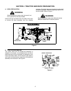
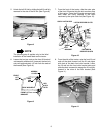
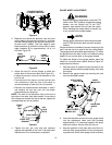
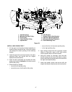
Figure 19
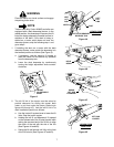
2. Measure and record the distance from the front
cutting edge to the ground (measure A), and from
the rear cutting edge to the ground (measure B),
for both outer blades. The front edge of each
blade (measure A) should be lower than its back
edge (measure B) by approximately 1/8 to 1/4
inch.See Figure 20.
Figure 20
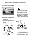
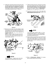
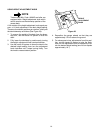
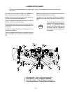
3. Adjust the front lift rod as follows to attain the
proper pitch of the mower deck (See Figure 21).
• Loosen the hex jam nuts and lock washers on the
front lift rod.
• From the front of the tractor, turn the front hex lock
nuts clockwise to raise the front of the deck, or
counterclockwise to lower the front of the deck.
• Recheck the measurements described in step 2
and readjust the hex lock nuts until the proper
measurements are obtained.
NOTE: The front lift rod should be fully to the front of
both slots in the deck front roller bracket. If one side of
the rod does not contact the front of the slot, tighten the
corresponding lock nut as needed.
Figure 21
4. Tighten the rear jam nuts and lock washers
against the backside of the front lift bracket after
adjustment of the rod has been completed.
GAUGE WHEEL ADJUSTMENT
WARNING
Before making any adjustments, place the PTO
switch in the “OFF” position, engage the parking
brakea, turn the ignition key to the “OFF”
position, and remove the key from the switch.
When handling the mower deck, be careful not
to cut yourself on the sharp blades.
NOTE
Gauge wheel adjustment should be performed
only AFTER the mower deck has been properly
leveled.
Gauge wheels are intended to prevent scalping of the
lawn, and are not to be used to set the cutting height.
The gauge wheels should be approximately 1/2" above
the ground when the deck is set in the desired cutting
height. Do not run the deck on the gauge wheels.
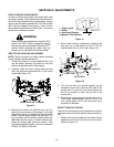
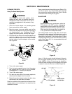
To adjust the height of the gauge wheels, place the
tractor on a firm and level surface. Refer to Figure 22,
and proceed as follows:
1. Use the tractor lift system to lower the deck to the
normally desired mowing height setting, then stop
the engine.
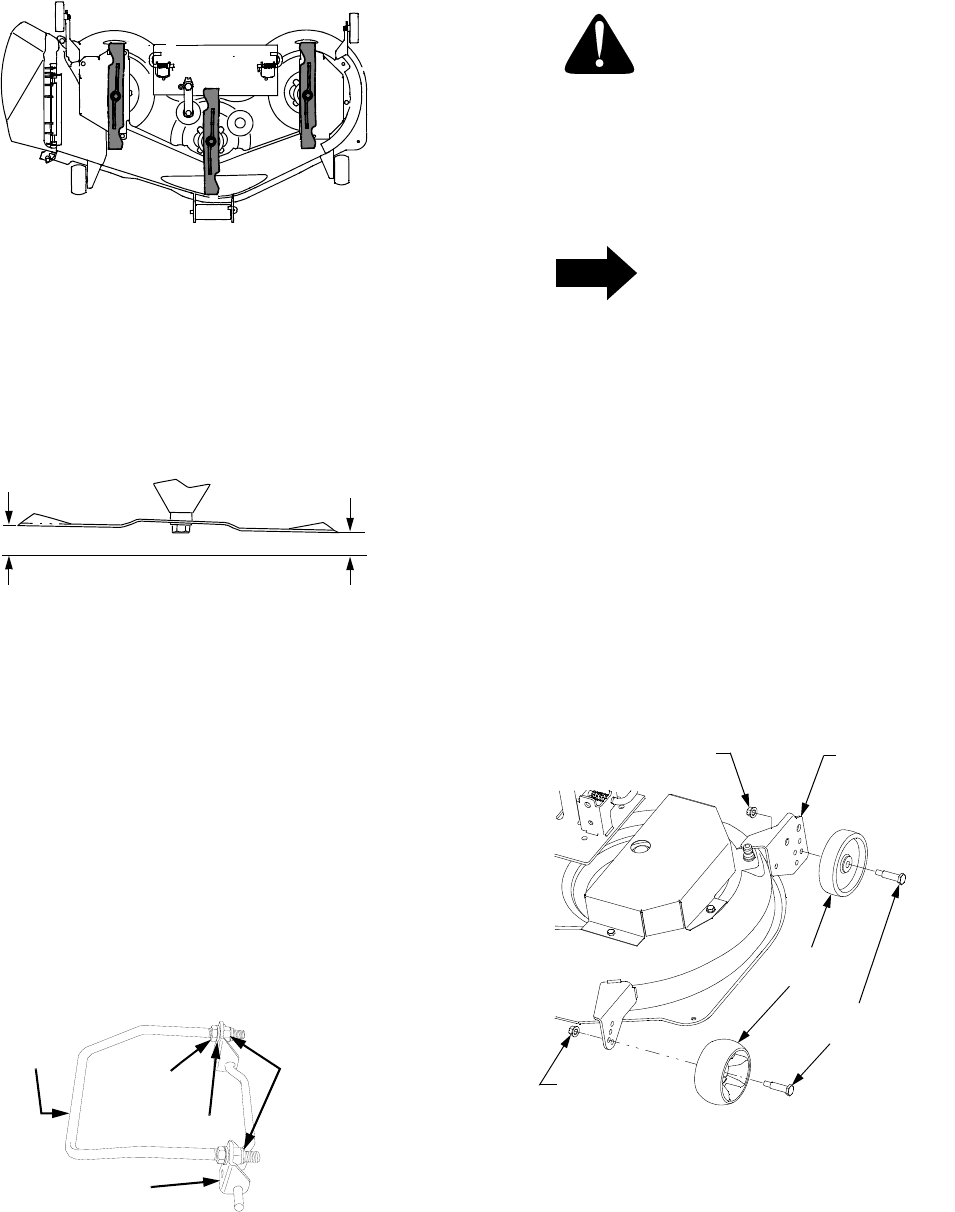
2. Remove the gauge wheels by removing the lock
nuts and shoulder screws.
Figure 22
3. Insert the shoulder screw with a rear gauge wheel
into the adjustment index hole that provides
approximately 1/2" clearance between the wheel
and level surface. Secure with the lock nut.
4. Note the position of the index hole used; then in-
stall the other gauge wheels into the correspond-
ing index hole of the other guage wheel brackets.
BLADES POINTING
TO FRONT AND REAR
A
B
FRONT
CUTTING
EDGE
REAR
CUTTING
EDGE
FRONT
LIFT
ROD
FRONT LIFT
BRACKET
HEX JAM NUT
LOCK WASHER
HEX
LOCK
NUTS
INDEX
BRACKET
HEX FLANGE
LOCK NUT
HEX FLANGE
LOCK NUT
GAUGE
WHEEL
SHOULDER
SCREW