


7
WARNING
Place the tractor on a level surface and engage
the parking brake lever.
NOTE
Tractors built Mfg. Code 1K060G and after are
equipped with a deck downstop feature. In the
raised position, the downstop will prevent the lift
links from being adequately lowered to allow in-
stallation of the deck. If the deck is being in-
stalled on a tractor which does not have the
downstop feature, skip the following step 1 and
go to step 2.
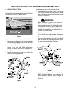
1. If installing the deck on a tractor with the deck
downstop feature, make certain the downstop is in
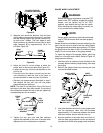
the lowered position as follows (See Figure 3):
a. If necessary, use the tractor’s lift handle to
raise the center lift and relieve any pressure
from the downstop arm.
b. Lower the deck downstop by continuously
turning the height adjustment knob counter-
clockwise.
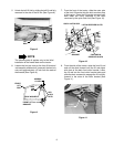
Figure 3
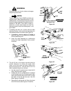
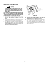
2. The left lift link of the tractor must be raised to
provide clearance for sliding the mower deck
under, or out from under, the tractor. Referring to
figures 4A through 4D, lock the left lift link in its
deck installation position as follows:
a. Use the tractor lift system lever to lower the lift
links. Stop the tractor engine.
b. Holding the left lift rod downward, lift upward
on the release tab of the lift stop bracket while
raising the rearward end of the lift link to align
the notch of the rod with the slot of the link
(See Figures 4A and 4B).
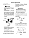
c. Swing the lift rod forward until fully to the front
of the lift link slot (See Figures 4C and 4D).
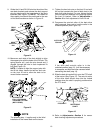
Figure 4A
Figure 4B
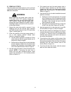
Figure 4C
Figure 4D
RAISE
LOWER
HEIGHT
ADJUSTMENT
KNOB
LEFT
LIFT
LINK
SLOT
VIEWED FROM
RIGHT SIDE
LIFT STOP BRACKET
RELEASE TAB
LEFT
NOTCH
LIFT
ROD
LIFT
UPWARD
HOLD
DOWN
SWING
LIFT ROD
FORWARD
LIFT LINK
LOCKED
VIEWED FROM
RIGHT SIDE