


10
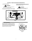
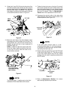
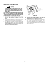
9. Guide the LH and RH lift links into the slots of the
rear deck brackets and release the deck support
pins by aligning with the inner holes of the deck
brackets (See Figure 12) NOTE: The handle of
the support pins should be positioned to the rear
of the deck brackets as shown in Figure 12.
Figure 12
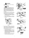
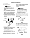
10. Maneuver each side of the deck slightly to align
the support pins with the holes of the lift links. The
spring tension will push the pins inward and, if
aligned, through the hole in each implement lift
link (See Figure 13).
NOTE: If unable to align the support pins with
the lift link holes, loosen the two hex lock nuts
on the front lift rod to allow the deck to be
moved farther rearward.
Figure 13
NOTE
The following step 11 applies only to the initial
installation of the mower deck on the tractor.
11. Tighten the hex lock nuts on the front lift rod until
the rod just contacts the front of both slots in the
deck front roller bracket. For now, tighten the hex
jam nuts and lock washers until just snug against
the front lift bracket. Refer to Adjustments—
Section 3 for final adjustment of front lift rod.
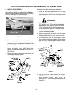
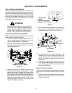
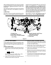
12. Compress the auto-lok collar of the deck drive
shaft rearward, then cock to lock the collar in the
released position (See Figure 14).
Figure 14
NOTE
If the drive shaft auto-lok collar is in the
unlocked position (step 12), it will be necessary
to compress and hold the collar rearward when
connecting the shaft (step 13).
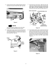
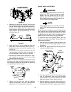
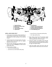
13. Slide the deck drive shaft fully onto the PTO shaft
of the tractor (See Figure 15). The auto-lok collar
of the drive shaft should snap into the locked
position when the shaft is properly positioned on
the PTO shaft.
Figure 15
14. Refer to Adjustments—Section 3 for mower
deck leveling adjustment procedures.
LIFT LINK
DECK
INNER
REAR
DECK
BRKT.
SUPPORT
PIN
SLOT
HOLE
SUPPORT PIN
FULLY EXTENDED
THROUGH LIFT LINK
(BOTH SIDES)
AUTO-LOK
COLLAR
COMPRESS
THEN COCK
TO LOCK
DECK DRIVE
SHAFT
PTO SHAFT