


9se c t i O n 4 — as s e M b l y , in s t a l l a t i O n & re M O v a l
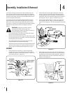
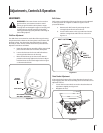
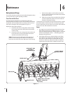
Make certain the support pins at the bottom of the front 4.
hitch yoke are in the engaged position (through holes in
yoke). See Figure 4-6.
Start the tractor and align the front hitch yoke with the 5.
attachment brackets on each side of the rear blower
housing (Refer to Figure 9).
Lower the front hitch yoke to clear the bottom of the 6.
attachment bracket pins and carefully drive the tractor
forward to align the bracket pins with the slots in the hitch
yoke (See Figure 4-7).
Using the tractor hydraulic system to raise the front 7.
hitch yoke, slowly lift the snow thrower until the hitch
support pins snap into the holes of the LH and RH housing
mounting brackets (See Figure 4-7).
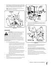
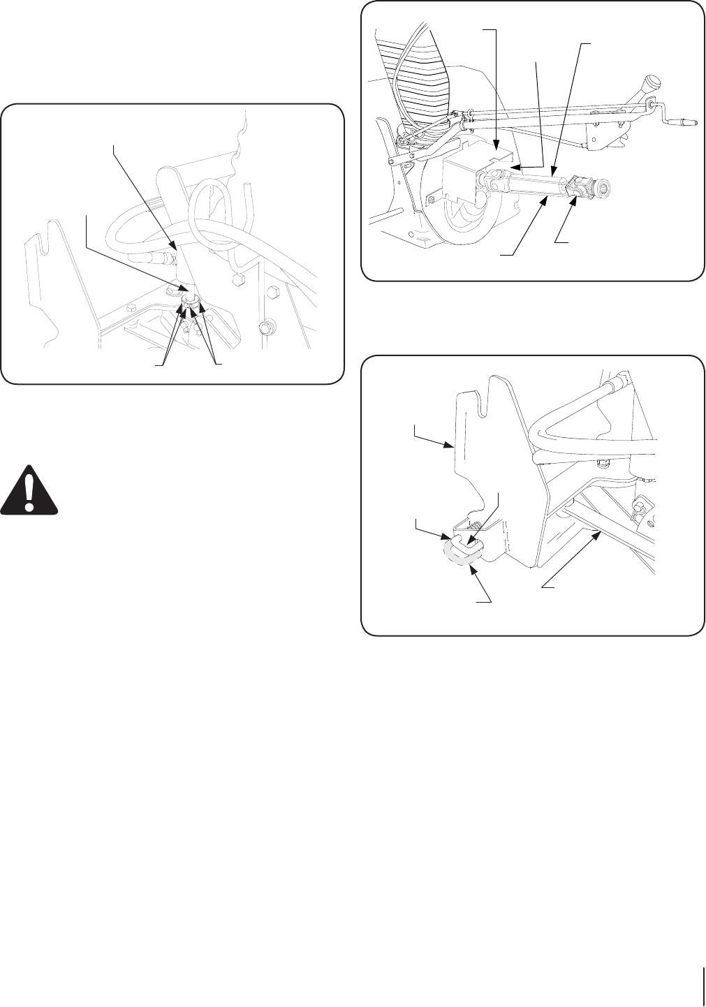
Remove the two socket head screws from the split locking 5.
collar assembly (6, Figure 3-2) and install the collar onto the
bottom of the piston of the front hitch lift cylinder. Secure
with the two socket head screws (See Figure 4-4).
NOTE: If necessary, use the tractor hydraulic system to
slightly extend the cylinder piston.
INSTALLATION
WARNING! If the Hydraulic Angling Kit (190-288-
100) is installed on the front hitch, accidental
actuation of the angling system could result in
damage to the snow thrower and/or tractor.
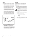
NOTE: Whenever the snow thrower is installed, it is
recommended that the angling cylinder be removed and
replaced by either the standard front hitch strut (See Figure 8)
or the manual angling kit (190-171), set in the center position.
The following step 1 applies ONLY to units equipped with the
hydraulic angling kit.
Remove the angling cylinder as follows: 1.
Compress the locking collars of the female fittings •
to disconnect the angling cylinder hoses from the
coupling assemblies on the left side of the tractor.
Remove the hoses from the hose support rod. •
Remove the internal cotter pins and clevis pins •
fastening the angling cylinder to the pivot plate
and the front hitch yoke.
Install the front hitch strut (or manual angler set in •
center position) with the clevis pins and internal
cotter pins. Refer to the Angling Kit Operator’s
Manual if necessary.
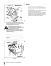
Cut the cable tie holding the two halves of the drive shaft 2.
together and slide the male half from the female half (See
Figure 4-5).
Pivot the female half shaft to the right and place in the slot 3.
in the right side of the shaft cover (See Figure 4-5).
HITCH LIFT
CYLINDER
CYLINDER
PISTON
SPLIT LOCKING
COLLAR
SOCKET HEAD
SCREWS
FEMALE
HALF
SHAFT
COVER
CABLE TIE
MALE
HALF
SHAFT
SLOT
SHAFT
COVER
ENGAGED
POSITION
DISENGAGED
FRONT
HITCH
YOKE
LH HITCH
SUPPORT
PIN
POSITION
STANDARD FRONT
HITCH STRUT
(FIXED LENGTH)
Figure 4-4
Figure 4-5
Figure 4-6