


Contents of Carton
3
6
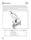
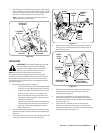
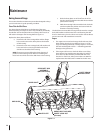
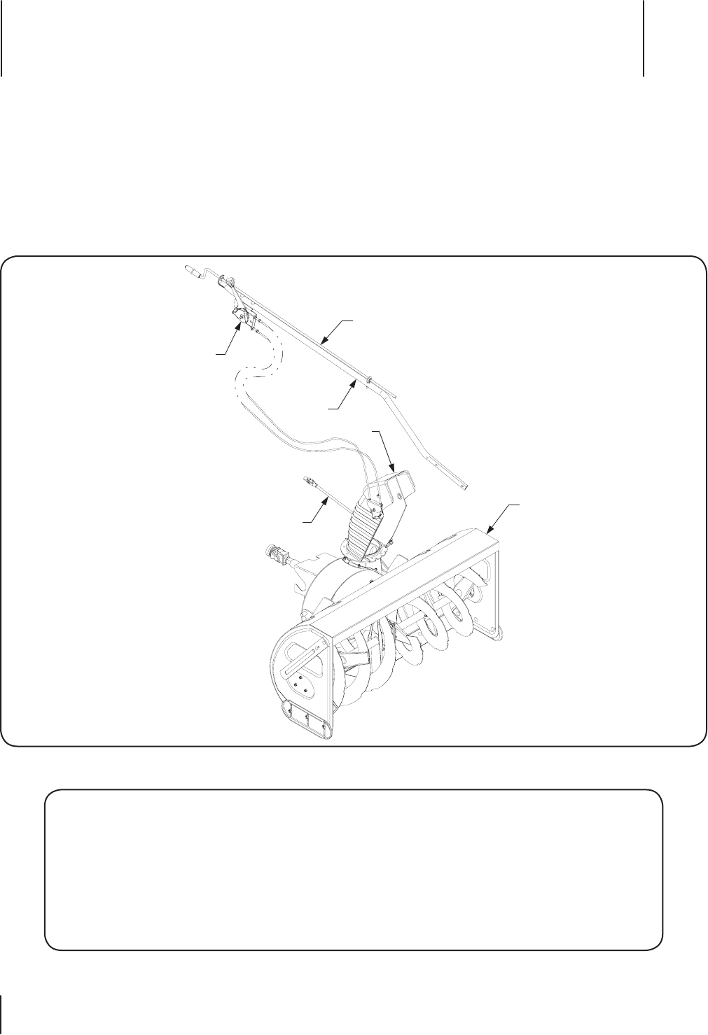
This section will help you to become familiar with the components of the 45” Snow Thrower Attachment, Model 190-353.
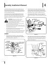
Select a firm level surface that is large enough to accommodate both the snow thrower assembly and the tractor with front hitch
assembly. After removing the upper crating material, remove the hardware pack and carefully roll the snow thrower assembly
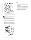
rearward so that it rests on its bottom. When repositioning the snow thrower, use care not to pinch or bind the chute crank support
tube (D, Figure 1). Cut the tie strap(s) and remove any packaging material from the chute crank rod/tilt handle/support tube assembly
(C thru E, Figure 1), then position to the left side of the snow thrower assembly.
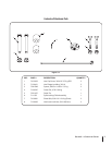
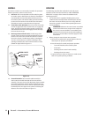
Refer to Figures 3-1 and 3-2 to confirm that all parts are present and to acquaint yourself with the part descriptions. Throughout the
instructions in this manual the parts shown in Figures 3-1 and 3-2 will be identified by name, followed by either their call-out letter or
number in parenthesis.
A
B
C
D
E
F
Figure 3-1
REF. DESCRIPTION QUANTITY
A Snow Thrower Assembly 1
B Discharge Chute Assembly 1
C Chute Tilt Handle Assembly 1
D Chute Crank Support Tube Assembly 1
E Chute Crank Rod Assembly 1
F Chute Crank/Mounting Bracket Assembly 1