


10 se c t i O n 4 — as s e M b l y , in s t a l l a t i O n & re M O v a l
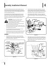
Stop the tractor engine and engage the parking brake. 8.
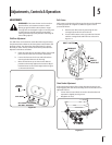
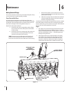
Check that support pins are fully engaged in the housing
mounting brackets holes (See Figure 4-7).
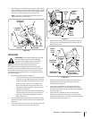
WARNING! If the tractor has been recently
operated, the muffler, exhaust pipe, and
surrounding areas will be HOT. Allow the tractor to
cool before beginning installation
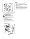
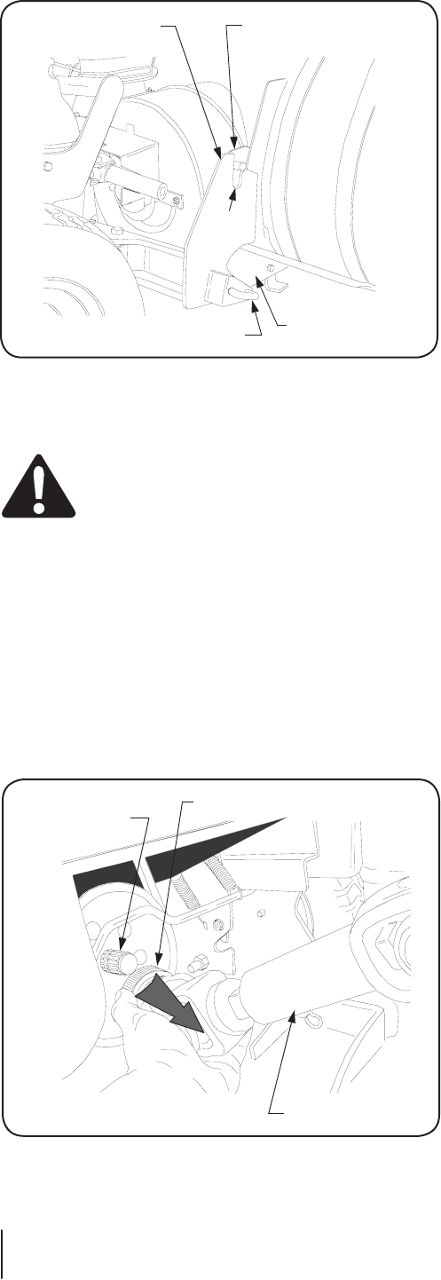
Pivot the female half shaft out of the cover slot and 9.
position so that it points rearward between the tractor
frame. Refer to Figure 4-8.
Slide the male half shaft into the female half 10.
Compress the auto-lock collar on the snow thrower drive 11.
shaft; then slide the shaft fully onto the PTO shaft of the
tractor and release the auto-lock collar (See Figure 4-8).
The drive shaft will lock onto the PTO shaft if properly
connected.
NOTE: It may be necessary to slightly rotate the drive shaft
to align the splines of the shafts.
REMOVAL
1. Move the snow thrower to its storage location.
2. Compress the auto-lock collar of the snow thrower drive
shaft and disconnect the shaft from the tractor PTO shaft.
Refer to Figure 4-8.
3. Pull the hitch support pins outward and rotate to lock in
the disengaged position. Refer to Figure 8.
4. Using the tractor hydraulic system, lower the front hitch
yoke to disengage the snow thrower attachment bracket
pins from the slots of the hitch yoke (Refer to Figure 4-7).
5. Back the tractor away from the snow thrower.
FRONT HITCH
RH ATTACHMENT
BRACKET
W/PIN
YOKE
SLOT
HITCH
SUPPORT PIN
RH HOUSING
MTG. BRACKET
YOKE
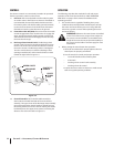
TRACTOR
PTO SHAFT
AUTO-LOK
COLLAR
DRIVE SHAFT
ASSEMBLY
C
O
M
P
R
E
SS
Figure 4-7
Figure 4-8