


Assembly, Installation & Removal
4
8
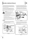
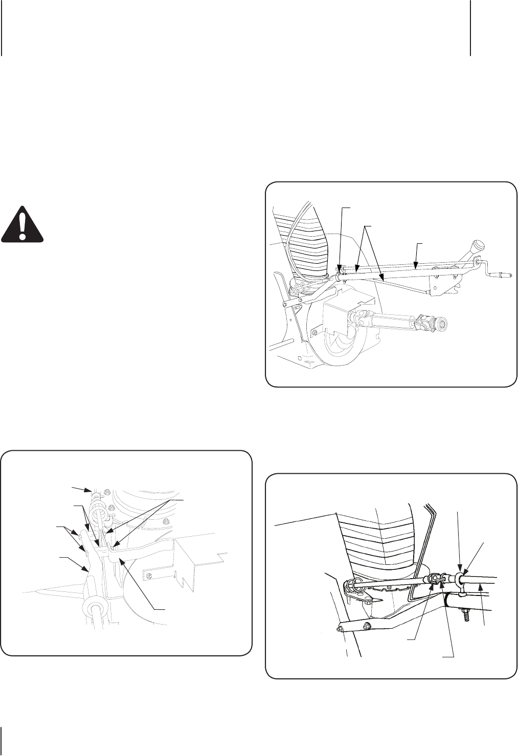
Position the chute crank support tube (D) to insert the 2.
screws (1, Figure 3-2) into the holes of the support tube
mounting bracket and the housing mounting bracket on
the left rear of the snow thrower housing. Secure with the
hex flange lock nuts (2 , Figure 3-2). Refer to Figure 4-1.
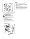
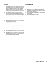
Secure the tilt handle cables (C , Figure 3-1) to the inside 3.
of the support tube (D , Figure 3-1) with the cable tie (5 ,
Figure 3-2). See Figure 4-2. Cut excess length from the cable
tie.
After making sure the chute crank rod is routed through 4.
the eye bolt, insert the rod (E, Figure 3-1) into the sleeve of
the joint block on the chute crank assembly (F , Figure 3-1).
Align the holes and secure the rod with the cotter pin (4 ,
Figure 3-2). See Figure 4-3.
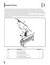
This section contains instructions for final assembly of the 45”
Snow Thrower, and the quick attachment steps for installation
and removal of the snow thrower. Before beginning, select a firm
and level surface large enough to accommodate both the snow
thrower attachment and tractor.
The mower deck and its front lift bracket assembly should be
removed from the tractor before installing the snow thrower.
Refer to the mower deck Operator’s Manual for deck removal
instructions. To remove (or install) the front lift bracket assembly
while the Front Hitch Kit Assembly is installed, proceed as
follows:
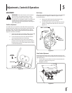
WARNING! If the tractor has been recently
operated, the muffler, exhaust pipe, and
surrounding areas will be HOT. Allow the tractor to
cool before beginning installation.
Loosen the hex lock nut (or wing-nut knob) securing the •
pivot pin on the left side of front hitch.
Remove the hex lock nut (or wing-nut knob) and pivot pin •
from the right side of the front hitch. Lower the right side of
the hitch pivot plate assembly.
Push downward on the tractor’s quick attach rod and •
remove the deck front lift bracket assembly.
Reposition the hitch pivot plate and install the RH pivot pin •
and hex lock nut (wing nut). Tighten the left hex lock nut.
Refer to the Front Hitch Operator’s Manual if necessary.
ASSEMBLY
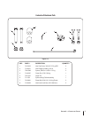
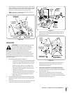
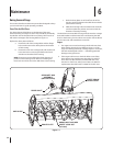
Insert the two hex cap screws (1 , Figure 3-2) through 1.
the holes at the forward end of the chute crank support
assembly (D , Figure 3-1), then slide a spacer (3 , Figure 3-2)
onto each cap screw (1 , Figure 3-2).
HEX FLANGE
LOCK NUTS
HEX CAP
SCREWS
SUPPORT
TUBE
MNTG. BRKT.
SPACERS
HOUSING
MNTG. BRKT.
CHUTE
CRANK
SUPPORT
CABLE TIE
TILT HANDLE
CABLES
SUPPORT
TUBE
BUSHING
EYE BOLT
COTTER PIN
JOINT
BLOCK
CHUTE
CRANK
ROD
Figure 4-1
Figure 4-2
Figure 4-3