


USE INSTRUCTIONS
GB
(GB) 3
GB
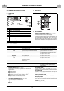
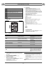
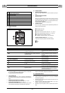
3.2 REAR PANEL
Figure 2.
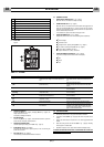
3.3 COMMAND FUNCTION
1.
POWER OUTPUT INDICATOR
(
Ref. 1
- Fig. 1 page 2)
When the LED is on, the machine is ready for cutting
2.
ALARM INDICATOR
(
Ref. 2
- Fig. 1 page 2)
When the LED is on, this means that one of the alarms has triggered, at the
same time the display (
Ref. 3
- Fig. 1 page 2) shows the type of alarm,
according to the table below, with relevant operations to be performed in
order to reinstate the power source.
In this condition the power source does not supply current.
3.
DIGITAL INSTRUMENT
(
Ref. 3
- Fig. 1 page 2)
displays the power source current or the following values temporarily:
✔
Start message.
✔
Software version.
✔
Voltage on torch, pressing the key
(Ref. 5
- Fig. 1 page 2) .
✔
Air pressure, pressing the key (
Ref. 6
- Fig. 1 page 2) .
✔
Type of alarm (ALARMS), see table 1.
✔
Type of machine error (FAIL) , see table 2.
4.
DIGITAL INSTRUMENT FUNCTION
(
Ref. 4
- Fig. 1 page 2)
The LED on corresponds to the value shown on the display:
✔
Volt.
✔
Amper.
✔
Bar.
TABEL n° 1 - ALARMS
5. CURRENT VOLTAGE KEY
Press the key (
Ref. 5
- Fig. 1 page 2) to display (
Ref. 3
- Fig. 1 page 2) the
voltage present on the torch.
The display of voltage is temporary.
6.
AIR FUNCTION KEY
Press the key (
Ref. 6
- Fig. 1 page 2) to activate the machine air system for
a fixed interval, with display of work pressure.
7. CURRENT ADJUSTMENT KNOB
Used for adjusting the cutting current (
Ref. 3
- Fig. 1 page 2) .
8.
START SWITCH
(
Ref. 8
- Fig. 2 page 3)
This switch has 2 positions On (Green light on) or Off, for switching the
power source on or off.
9.
AIR FILTER
(
Ref. 9
- Fig. 2 page 3)
clean according to scheduled maintenance instructions.
4.0 USE INSTRUCTIONS
a. Connect the power source in a dry place with suitable ventilation.
b. Press the On switch (
Ref. 8
- Fig. 2 page 3) and wait for the power source
to start.
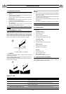
c. Position the earth clamp on the piece to be cut, ensuring good electrical
contact.
d. Select the cutting current with the knob (
Ref. 7
- Fig. 1 page 2) following
the data given in the table below.
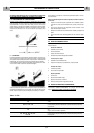
e. Approach the piece to be cut, press the torch button and begin cutting.
TO A
VOID ELECTRODE AND NOZZLE WEAR, IT IS ADVISABLE NOT TO KEEP THE
PILOT ARC ACTIVATED IN THE AIR.
1
Power output indicator
2
Alarm indicator
3
Digital instrument
4
Digital instrument function (Volt - Amp. - Bar)
5
Voltage - current function key
6
Air function key
7
Adjustment knob
8
On switch
9
Filter
DISPLAY
MEANING RESETTING
- - -
Insufficient input voltage. Line switch open or no
line.
When the alarm ceases.
If the alarm persists, contact the assistance cen-
tre.
CUP
The torch cap is not properly tightened (With
power source on).
Switch the power source off.
Tighten the cap correctly and restart the power
source.
HtA
Power converter overtemperature.
When the alarm ceases (When the internal tempe-
rature has fallen).
ThA
(Flashing)
Warning of approaching power converter over-
temperature (HtA).
When the alarm ceases (When the internal tempe-
rature has fallen).
CtA
Compressor overtemperature.
When the alarm ceases (When the internal tempe-
rature has fallen).
Air
Insufficient air pressure
(Less than 1.5 bar).
Contact the assistance centre.
ScA
Short circuit on output. Switch the power source off and then on again.
LSF
Arc blows out.
Check wear of cap and electrode and replace if
necessary. If the alarm persists switch the power
source off and then on again. If the alarm occurs
again, call the assistance centre.