


TECHNICAL DESCRIPTION
GB
(GB) 2
GB
1.0 TECHNICAL DESCRIPTION
1.1 DESCRIPTION
The system is a modern direct current generator for plasma arc cutting, created
thanks to the application of the inverter.
This special technology allows for the construction of compact light weight gener-
ators with high performance.
Possibility of adjustment, high efficiency and reduced power consumption make it
an excellent tool, able to perform quality cutting up to thicknesses of 6 mm.
The generator has an integrated compressor, and therefore does not require con-
nection to any compressed air supply.
The generator is equipped with automatic arc restart, which enables optimum cut-
ting of metal grid structures.
The generator also has safety systems that inhibit the power circuit when the
operator comes into contact with live parts of the machine.
Cutting of thicknesses up to 2 mm with just the pilot arc is also possible; this is
very useful with painted metals to which the positive pincer cannot be connected.
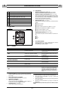
1.2 TECHNICAL SPECIFICATIONS
DATA PLATE
1.3 ACCESSORIES
Consult the area agents or the dealer.
1.4 DUTY CYCLE
The duty cycle is the percentage of 10 minutes that the power source can cut at its
rated current, considering an ambient temperature of 40° C, without the thermo-
static protector cutting in. If it does cut in, the user has to wait for power source
reinstatement before resuming cutting (see page IV).
DO NOT EXCEED THE MAXIMUM WORK CYCLE.
Exceeding the work cycle specified on the dataplate can damage the power source
and invalidate the warranty.
2.0 INSTALLATION
IMPORTANT: Before connecting, preparing or using equipment,
read section SAFETY PRECAUTIONS.
2.1 CONNECTING THE POWER SOURCE TO THE MAINS
ELECTRICITY SUPPLY.
Check that the power socket is equipped with the fuse indicated in
the technical data table on the power source. All power source models are
designed to compensate power supply variations. For variations of +-10%, a
cutting current variation of +-0,2% is created.
2.2 POWER SOURCE POSITIONING
Special installation may be required where gasoline or volatile
liquids are present. Contact the competent authorities. When positioning
equipment, ensure that the following guidelines are followed:
1. The operator must have unobstructed access to controls and equipment
connections.
2. Check that the power cable and fuse of the socket for power source connec-
tion is suited to current requirements of the latter.
3. Do not position equipment in confined, closed places. Ventilation of the
power source is extremely important. Avoid dusty or dirty locations, where
dust or other debris could be aspirated by the system.
4. Equipment (including connecting leads) must not obstruct corridors or
work activities of other personnel.
5. Position the power source securely to avoid falling or overturning. Bear in
mind the risk of falling of equipment situated in overhead positions.
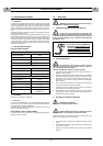
2.3 HANDLING AND TRANSPORTING THE POWER SOURCE
OPERATOR PROTECTION:
Welder’s helmet - Gloves - Safety Shoes - Gaiters.
The welding power source does not weigh more than 25 Kg and
can be handled by the operator. Read the following precautions carefully.
The power source has been designed for lifting and transport. However, the fol-
lowing procedures must always be observed:
1. The operations mentioned above can be carried out by means of the handle
on the power source.
2. Disconnect the power source from the power supply and all accessories
before liftling or moving. Do not drag, pull or lift equipment by the cables.
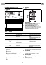
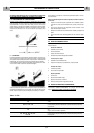
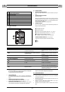
3.0 CONTROLS: LOCATION AND FUNCTION
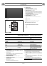
3.1 FRONT PANEL
Figure 1.
PRIMARY
Single phase voltage 230V
Frequency 50 / 60 Hz
Effective consumption 11A
Maximum consumption 16A
SECONDARY
Voltage under no load 300V
Cutting current 10 ÷ 20A
Duty cycle 20A ÷ 50%
Protection class IP 23
Insulation class H
Weight 12 kg.
Dimensions mm 410 x 180 x 310
Europeans Standards
EN 60974.1 - EN 60974.7
EN 60974.10
BEFORE INSERTING THE MAINS PLUG, IN
ORDER TO AVOID DAMAGE TO THE POWER
SOURCE, CHECK THAT THE MAINS CORRE-
SPONDS TO THE REQUIRED POWER SUPPLY.
3
6
7
4
1
2
5