


19
MAINTENANCE
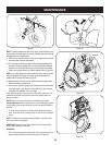
Figure 27
Figure 28
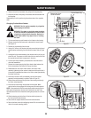
Figure 29
Figure 30
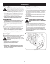
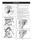
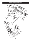
NOTE: The pulley adapter may slide off the auger input shaft when remov-
ing the pulley. Use extra caution to ensure the adapter does fall and/or get
damaged when removing the pulley.
11. Place the new auger belt in the V-groove of the auger pulley and place
the pulley w/belt inside the belt keepers.
12. Turn the pulley as necessary to align its three slots approximately with
the posts of the pulley adapter, then move the brake bracket assembly
away from the input shaft. While aligning the pulley slots and adapter
posts, push the auger pulley fully onto the adapter. Refer to Figure 29.
NOTE: If the pulley adapter was removed with the pulley, align the splines
of the pulley adapter and auger input shaft, and push the pulley and
adapter onto the input shaft. Refer to Figure 29.
13. Slide the washer onto the hex screw removed earlier and apply Loctite
262 to the threads of the hex screw.
14. Insert the hex screw through the pulley assembly and into the threads
of the input shaft. Torque the hex screw to 250-325 in./lbs. to secure
the auger pulley assembly on the input shaft.
If also replacing the drive belt, proceed to the “Drive Belt” instruction. If not,
reassemble by performing the previous steps in the opposite order and
manner of removal.
NOTE: Make sure to remove the piece of wood blocking the impeller.
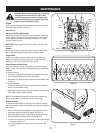
Proper Adjustment: With the auger clutch lever in the disengaged position,
the top surface of the new belt should be even with the outside diameter of
the pulley.
1. To adjust, disconnect ferrule from brake bracket assembly and thread
ferrule in (towards idler) to increase tension on belt, and out to decrease
tension.
NOTE: The brake puck must always be firmly seated in the pulley groove
when auger control is disengaged.
IMPORTANT: Repeat the “Auger Drive Control Test” from the Assembly
section before operating snow thrower.
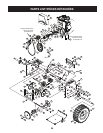
Drive Belt
1. Pull the idler pulley away from the backside of the drive belt to relieve the
tension and slide the drive belt off the idler pulley. See Figure 30.
a
c
b
Adapter
Slots
1b
2
1a
3