


17
MAINTENANCE
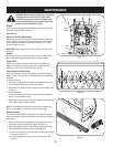
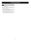
Figure 19
WARNING: Before lubricating, repairing, or inspecting,
disengage all clutch levers and stop engine. Wait
until all moving parts have come to a complete stop.
Disconnect spark plug wire and ground it against the
engine to prevent unintended starting.
Engine
Refer to the separate engine manual packed with your unit for all engine
maintenance and lubrication instructions.
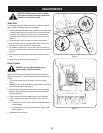
Lubrication
Drive and Shifting Mechanism
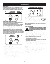
At least once a season or after every 25 hours of operation, remove rear
cover. Lubricate any chains, sprockets, gears, bearings, shafts, and the
shifting mechanism at least once a season. Use engine oil or a spray
lubricant. Refer to Figure 19.
IMPORTANT: Keep all grease and oil off the rubber friction wheel and
drive plate.
Wheels
At least once a season, remove both wheels. Clean and coat the axles
with a multipurpose automotive grease before reinstalling wheels.
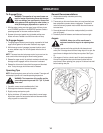
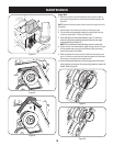
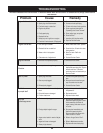
Auger Shaft
At least once a season, remove the shear pins on auger shaft. Spray
lubricant inside shaft, around the spacers. Also lubricate the flange
bearings found at either end of the shaft. See Figure 20.
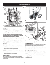
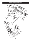
Shave Plate and Skid Shoes
The shave plate and skid shoes on the bottom of the snow thrower are
subject to wear. They should be checked periodically and replaced when
necessary.
To remove skid shoes:
1. Remove the carriage bolts (and washers if equipped)and hex flange
nuts which secure the skid shoes to the snow thrower.
2. Reassemble new skid shoes with previously removed hardware. Refer
to Figure 21.
To remove shave plate:
1. Remove the carriage bolts and hex nuts which attach it and the skid
shoes to the snow thrower housing.
2. Reassemble new shave plate, making sure heads of carriage bolts are
to the inside of housing. Tighten securely.
NOTE: The reversible skid shoes may be turned over to increase their
lifespan. If steel shoes are turned they must also change sides.
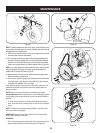
Replacing Belts
To remove and replace either the auger belt or the drive belt, follow the
steps below and then proceed to the specific steps listed under respective
sub-headings.
1. Disconnect the chute crank assembly at the discharge chute end by
removing the hairpin clip and the flat washer. See Figure 18.
2. Remove the plastic belt cover, located near the engine, by removing
the three self-tapping screws that secure it. See Figure 22.
3. a. Loosen the bolt shown in Figure 23 securing the belt keeper bracket
and remove the other bolt.
b. Push the belt keeper and bracket up off the engine pulley. See
Figure 24.
Friction
Wheel
Drive
Plate
Gear
(Hex)
Shaft
Figure 21
Figure 20