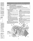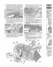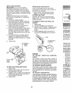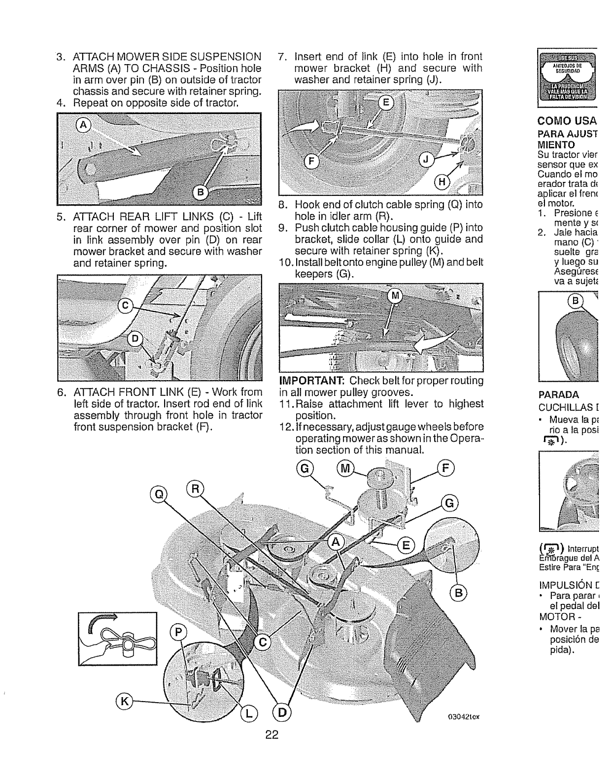
3. ATTACH MOWER SIDE SUSPENSION
ARMS (A) TO CHASSIS - Position hole
in arm over pin (B) on outside of tractor
chassis and secure with retainer spring.
4. Repeat on opposite side of tractor,
.
ATTACH REAR LIFT LINKS (C) - Lift
rear corner of mower and position slot
in link assembly over pin (D) on rear
mower bracket and secure with washer
and retainer spring.
,
Insert end of link (E) into hole in front
mower bracket (H) and secure with
washer and retainer spring (J).
8. Hook end of clutch cable spring (Q) into
hole in idler arm (R).
9. Push clutch cable housing guide (P) into
bracket, slide collar (L) onto guide and
secure with retainer spring (K),
10. Install belt onto engine pulley (M) and belt
keepers (G).
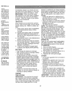
COMO USA
PARA AJUS'f
MIENTO
Su tractor vier
sensor que ex
Cuando el mo
erador trata d_
aplicar el frem
et motor.
1. Presione
mente y sc
2. Jale hacia
mano (C)'
suelle gra
y luego su
Aseg_res_
va a sujet_
6,
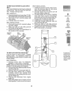
ATTACH FRONT LINK (E) - Work from
left side of tractor. Insert rod end of link
assembly through front hole in tractor
front suspension bracket (F).
IMPORTANT: Check belt for proper routing
in all mower pulley grooves.
11.Raise attachment lift lever to highest
position.
12. If necessary, adjust gauge wheels before
operating mower as shown in the Opera-
tion section of this manual.
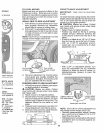
PARADA
CUCHILLAS [
• Mueva la p_
rio ata posi
22
03042Le_
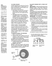
(1_) Interrupt
Er_rague del A
Estire Para "Enc.
IMPULSION E
• Pare parer
el pedal del
MOTOR *
• Mover la pa
posici6n de
pida).


