


HOW TO SET UP YOUR SNOW
THROWER
NOTE: Place fuel stabilizer In a safe
place untll needed for storage.
• Remove top pallet from carton.
• Cut and discard the plastic ties securing
the chute rod to the upper pallet and
place aside. Discard pallet.
• Cut all four comers of the carton from top
to bottom and lay the panels flat.
• Cut the bands holding the snow thrower
to the lower pallet.
• Remove snowthmwer from lower pallet.
• Remove the packing material from the
handle assembly and all protective
material from the unit and discard.
• Cut ties securing the clutch control
cables.
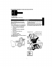
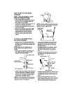
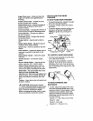
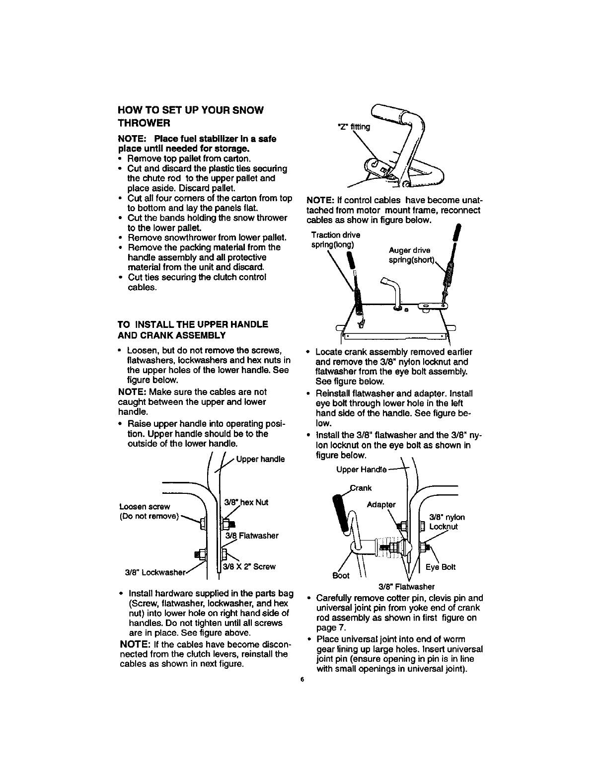
"z" fitting
NOTE: If control cables have become unat-
tached from motor mount frame, reconnect
cables as show in figure below.
Tractiondrive I
spdng(Iong)
i Augerdrive
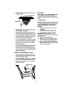
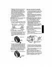
TO INSTALLTHE UPPER HANDLE
AND CRANKASSEMBLY
• Loosen, but do not remove the screws,
flatwashers, leckwashers and hex nuts in
the upper holes of the lower handle. See
figure below.
NOTE: Make sure the cables are not
caught between the upper and lower
handle.
• Raise upper handle into operating posi-
tion. Upper handle should be to the
outside of the lower handle.
--_t _/" Upper handle
Loosenscrew _'_'hex
Nut
(Do notremove)
I;
_8Flatwasher
t"
Lockwasher//_ 3/8 X 2"Screw
3/8"
• Install hardware supplied in the parts bag
(Screw, flatwasher, Iockwasher, and he:<
nut) into lower hole on right hand ,side of
handles. Do not tighten untilall screws
are in place. See figure above.
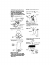
NOTE: If the cables have become discon-
nected from the clutch levers, reinstall the
cables as shown in next figure.
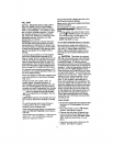
Locate crank assembly removed earlier
and remove the 3/8" nylon Iocknut and
flatwasher from the eye bolt assembly.
See figure below.
Reinstall flatwasher and adapter. Install
eye bolt through lower hole in the left
hand side of the handle. See figure be-
low.
install the 3/8" flatwasher and the 3/8" ny-
lon Iocknut on the eye bolt as shown in
figure below.
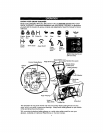
3/8"nylon
Locknut
Eye Bolt
Boot
3/8" Flatwasher
• Carefully remove cotter pin, clevis pin and
universal joint pin from yoke end of crank
rod assembly as shown in first figure on
page 7.
• Place univemal joint into end of worm
gear lining up large holes. Insert universal
joint pin (ensure opening in pin is in line
with small openings in universal joint).
6