


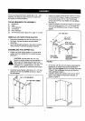
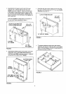
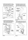
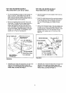

Assemblethe engine base assembly to the welded
angles on the tongue using four 5/16" x 3/4" hex bolts,
5/16" lock washers and 5/16' hex lock nLRs. NOTE:
Use the upper set of holes inthe welded angles.
Make sure bolts are securely tightened. See figure 20.
Mount the chipper chute assembly onto the three
weld bolts located on the back side of the blower
housing assembly. Fasten with three 5/16" bell
washers (cupped side against chute assembly) and
three 5/16" locknuts. Tighten securely. See figure
22.
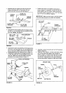
ENGINE
BASE
5EMBLY
5/16"LOCK
, WASHER
I'
5/16" HEX LOCK NUT------.._ 16" x 3/4"
HEX BOLT
l
RF.AR
WELDEDANGLES
i
FIGURE 20
FRONT
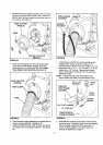
To assemble the hosehanger bracket to the blower
housing,you mustfirst remove two selftapping
screws from the holes inthe blower housing as shown
in figure 21. Using these same screws, attach the
hose hanger bracket to the blower housing.
5/16" x 3/4" SELF
TAPPING SCREWS
HOSE
HANGER
BRACKET
FIGURE 21
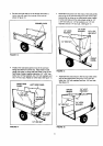
CHIPPER CHUTE
ASSEMBLY
5/16" WELD BOLTS
(FOUND ON BACK
5/16" LOCK NUT
/
.--'"_'_ 5116" BELL
WASHER
'FIGURE22
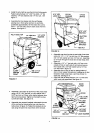
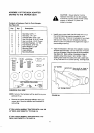
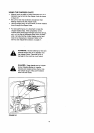
• Assemble the eibow to the blower housing, using four
5/16" x 3/4' self tapping hex bolts, and four nylon
washers. Tighten bolts securely. See figure 23.
NYLON
WASHER
5/16" x 3/4"_
HEXBOLT [
(SELF TAP)
FIGURE 23
12