


12
OPERATION
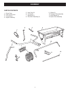
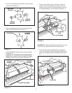
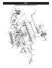
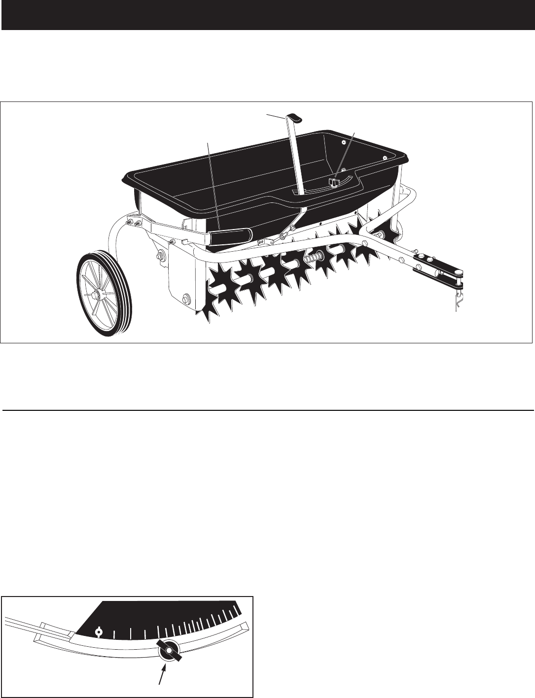
KNOW YOUR SPIKER SPREADER
Read this owner's manual and safety rules before operating your Spiker Spreader.
Compare the illustration below with your Spiker Spreader to familiarize yourself with the various controls and their
locations.
FLOW CONTROL LEVER Opens and closes the ow
plate at the bottom of the hopper.
LIFT HANDLE Raises the unit for transport or lowers it
for spreading and aerating.
PLASTIC WING NUT Tightens at desired setting to
control how far the ow control lever can open the ow
plate.
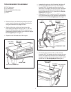
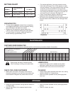
HOW TO USE YOUR SPIKER/SPREADER
• Refer to the instruction label on the material package
and to the instruction decal on your spreader to help
determine the proper spreader setting and application
rate. Also see the Setting Chart on page 13 of this
manual for a general range of settings for commonly
used materials.
• Determine the approximate square footage of the
area to be covered and estimate the amount of
fertilizer or seed required.
• Move the spreader to the area where application is to
begin.
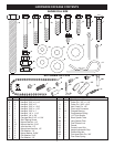
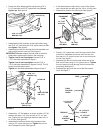
FIGURE 24
FLOW CONTROL LEVER
PLASTIC WING NUT
LIFT HANDLE
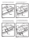
• Loosen the plastic wing nut and move it to the desired
setting. Retighten the nut. See gure 24.
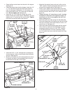
• Making sure the ow control lever is in the "OFF"
position, ll the hopper, breaking up any lumps.
• Lower the aerator spikes to the operating position.
• Start the spreader in motion and then move the
ow control lever to the "ON" position (against the
plastic wing nut) as you travel across your lawn. The
recommended towing speed is 3 m.p.h.
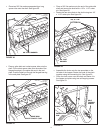
• Do not make sharp turns with spikes in the ground.
• Raise aerator spikes to transport position when
crossing over concrete or other hard surfaces.
• Do not aerate if the ground is extremely hard or dry.
If ground is too dry, sprinkle or water for one to two
hours prior to use.
• Do not aerate if the ground is too wet (muddy).
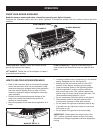
IMPORTANT: Always place ow control lever in the
"OFF" position to prevent excess fertilizer from being
released when lling the spreader and when stopping or
turning.
ALIGN AND TIGHTEN WING NUT
AT DESIRED FLOW SETTING
1
2
3
4
5
6
7
8
9
10
11
12
13
14
15
16 17
18
OFF
0
WING NUT SET AT "5"