


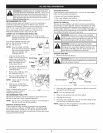
AdjustIdleSpeedScrew 5. Cleandirtfromaroundthe
WARNING:Thecuttingattachmentmayspinduring
idlespeedadjustments.Wearprotectiveclothingand
observeallsafetyinstructionstopreventserious
personalinjury.
If,aftercheckingthefuelandcleaningtheairfilter,theengine
stillwillnotidle,adjusttheidlespeedscrewasfollows:
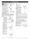
1. Starttheengineandletit runatahighidleforaminuteto
warmup.Refer to Starting/Stopping Instructions.
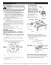
2. Release the throttle trigger and let the engine idle. If the
engine stops, insert a small phillips screwdriver in between
the Air Filter Cover and the Engine Cover (Fig. 30). Turn the
idle speed screw in, clockwise, 1/8 of a turn at a time (as
needed) until the engine idles smoothly.
NOTE: The cutting attachment should not rotate when the
engine idles.
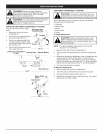
3. If the cutting attachment rotates when the engine idles,
turn the idle speed screw counterclockwise 1/8 of a turn at
a time (as needed), until the attachment stops turning.
Checking the fuel, cleaning the air filter, and adjusting the idle
speed should solve most engine problems. If not and all of the
following are true:
• the engine will not idle
the engine hesitates or stalls on acceleration
there is a loss of engine power
Have the carburetor adjusted by a Sears or other qualified
service dealer.
ROCKER ARM CLEARANCE
This requires disassembly of the engine. If you feel unsure or
unqualified to perform this, take the unit to a Sears or other
qualified service dealer
NOTE: Inspect the valve to rocker arm clearance with a feeler
gauge after the first 10 hours of operation and every
25 hours of operation.
The engine must be cold when checking or adjusting the
valve clearance.
This task should be performed inside, in a clean, dust free
area.
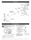
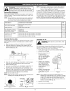
1. Remove the six (6) screws on the back of the engine cover
with a Flat-head or T-25 Torx screwdriver (Fig. 31).
View Of The Rear Engine Cover
Remove
Screws
2,
3.
[ ]
[ I
[ ]
Remove
Screws
Fig.31
Disconnect the spark plug wire.
Clean dirt from around the spark plug. Remove the spark
plug from the cylinder head by turning a 5/8 in. socket
counterclockwise.
rocker arm Cover. Remove
the screw holding the rocker Rocker
arm cover with a large flat Arm
blade screwdriver or Torx T- Cover
25 bit (Fig. 32). Remove the \
rocker arm cover and gasket.
\
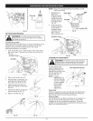
6. Pull the starter rope slowly to Spark
bring the piston to the top of Plug
its travel, (known as top dead Hole
center). Check that:
The piston is at the top of its
travel while looking in the spark
plug hole (Fig. 33)
Both rocker arms move freely,
and both valves are closed.
Rocker Arms INTAKE
Fig. 32
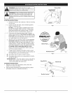
Adjusting Nuts
EXHAUST
Feeler Gauge
Spark Flug
Hole
Fig. 33
If these statements are not true, repeat this step.
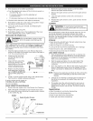
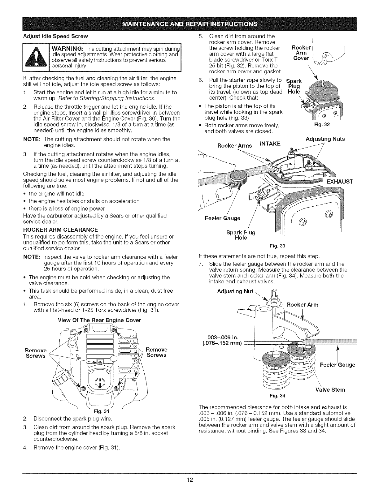
7. Slide the feeler gauge between the rocker arm and the
valve return spring. Measure the clearance between the
valve stem and rocker arm (Fig. 34). Measure both the
intake and exhaust valves.
Adjusting
.003-.006 in.
(.076-.152 mm
Rocker Arm
C
Valve Stem
The recommended clearance for both intake and exhaust is
.003 - .006 in. (.076 - 0.152 mm). Use a standard automotive
.005 in. (0.127 mm) feeler gauge. The feeler gauge should slide
between the rocker arm and valve stem with a slight amount of
resistance, without binding. See Figures 33 and 34.
4. Remove the engine cover (Fig. 31).
t2