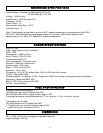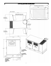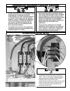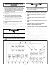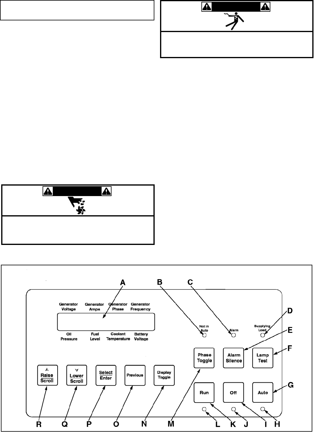
A Two line by twenty character LCD provides the
primary visual interface for metering, alarms, pre-
alarms and protective functions. In the normal mode,
labels appear above and below the display. In the
alternate display mode, labels and the displayed
value appear on the display.
B Red LED turns ON when the device is not in the
AUTO mode.
C Red LED turns ON continuously for all alarm
conditions and flashes for pre-alarm conditions.
D Green LED turns ON when the generator is
supplying more than two percent of generator full
load rated current.
E Pushbutton used to silence an optional audible
alarm.
F Pushbutton used to exercise all segments of the
LCD and to illuminate all LED’s.
G Pushbutton used to place the device in AUTO mode.
H Green LED turns ON when the device is in the AUTO
mode.
I Pushbutton used to place the unit in the OFF mode.
J Red LED turns ON when the device is in the OFF
mode.
K Pushbutton used to place the device in the RUN
mode.
L Green LED turns ON when the device is in the RUN
mode.
M Pushbutton used to scroll through the displays
available in the normal display mode.
N Pushbutton used to scroll through the display modes.
O Pushbutton used to scroll through previous menu
levels.
P Pushbutton used to enter menu sublevels and select
set points.
Q Pushbutton used to scroll backward through the
menus and to decrement set points.
R Pushbutton used to scroll forward through the menus
and to increment set points.
G
G
E
E
N
N
E
E
R
R
A
A
T
T
O
O
R
R
C
C
O
O
N
N
T
T
R
R
O
O
L
L
P
P
A
A
N
N
E
E
L
L
F
F
E
E
A
A
T
T
U
U
R
R
E
E
S
S
WWAARRNNIINNGG
• With the Mode switch in the Auto position, the
unit starts and stops without notice.
• Keep clear of all moving parts at all times.
WWAARRNNIINNGG
• Place the circuit breaker in the OFF position
when servicing the generator to minimize
electrocution hazards.
Generator Control Panel
14


