


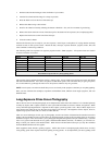
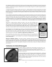
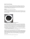
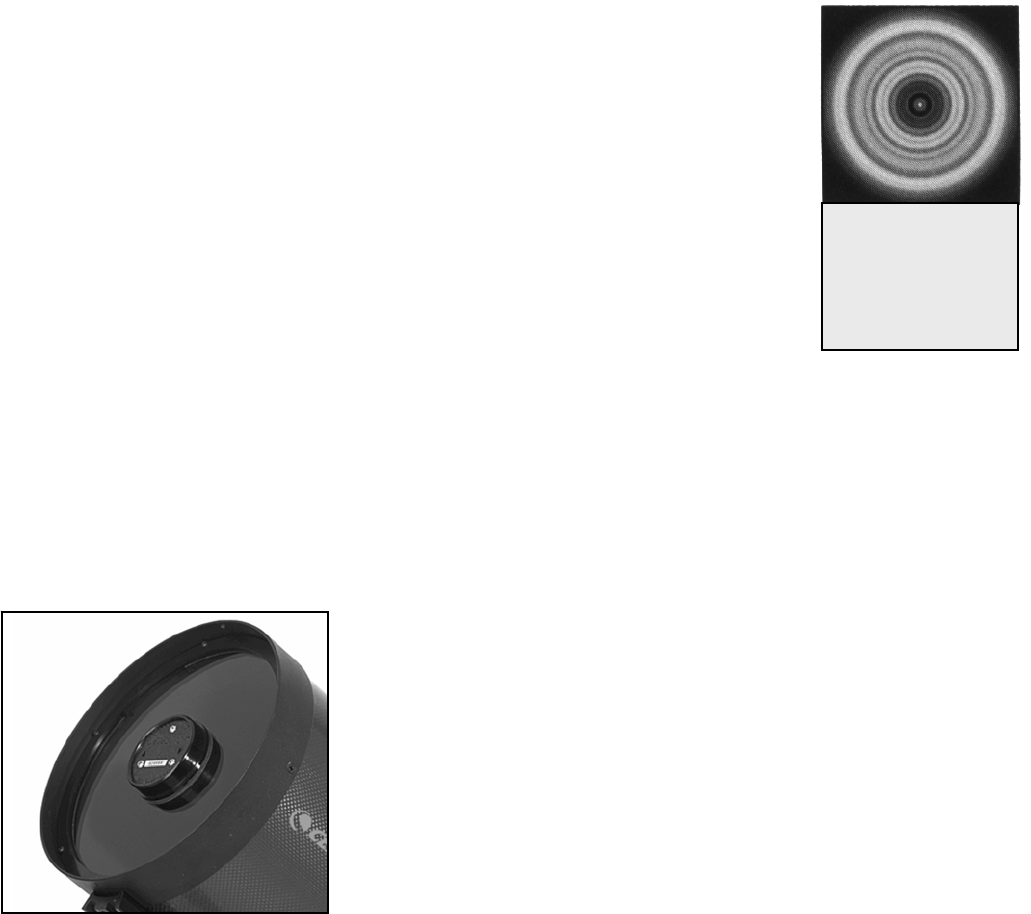
Figure 7-2
similar to the diffraction
Pick a bright star and center it in the field of the telescope. Study the image of the star while racking it in and out of focus using
focus pattern is present, then collimation is
ear as a concentric ring pattern similar to
is approximately polar aligned
r pointed at a stationary star without the motor drive running. Polaris, the North Star, is the perfect collimation star for northern
bove the northern horizon is always equal
your latitude angle.
n the objective lens housing on the front of the tube. (These screws
make an
other which screws are correctly turned and by
justment, it is necessary to re-aim the telescope tube to center the star
ets of screws to
bumped or jarred severely. In fact, most observers will find the telescope’s collimation right out
efractor includes a collimating eyepiece that can help you to roughly check the
collimating e
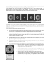
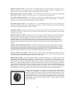
roperly aligned with the tube. With the focuser racked in all the way and the diagonal removed, place the collimating eyepiece
ed, you should be able to see the entire edge of the objective lens
pears oval, then it may be necessary to collimate the telescope as
an eyepiece that yields 30 to 60 power for every inch of aperture. If an unsymmetrical
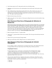
necessary. (If the telescope is properly collimated, the out of focus star image will app
that shown in Figure 7-2).
To collimate, the telescope should be on either a motor driven (i.e., tracking) equatorial mount that
o
hemisphere observers since it appears motionless against the background sky long enough to perform the collimation procedure.
Polaris is the last star in the handle of the Little Dipper (Ursa Minor) and its distance a
to
rior to collimating, locate the three (3) mounting screws o
P
attach the objective lens housing to the main tube and should not be removed). It may be necessary to remove the lens shade from
the front of the tube to allow easy access to the collimation screws. Next to each mounting screw is a shorter Allen screw
ollimation screw) that pushes against the optical tube to pivot the objective lens housing (see Figure 7-1). In order toc
adjustment, the mounting screw is loosened while the Allen screw is turned in or out. Then, the mounting screw is tightened.
Only one of the three (3) sets is adjusted at a time. Normally motions on the order of 1/8 turn will make a difference, with only
about 1/2 to 3/4 turn being the maximum required.
Do NOT remove or back out the holder screws more than one (1) to two
(2) turns!
With Polaris or another bright star centered in the field of view, focus with your highest power
eyepiece (i.e., one with the shortest focal length). This includes eyepieces in the 4mm to 6mm range.
The star should be well centered in the field of view of the eyepiece. It may be helpful for two people
orking together, while one views and instructs the
w
how much. Start by loosening the Phillips head (mounting) screws about 1 turn and advancing the
Allen screw to see if the motion is correct. If not, undo what you did and try another set of screws.
fter making the first of each ad
A
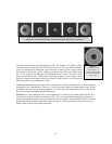
A collimated telescope
should appear as a
symmetrical ring pattern
achieve the necessary lens movement. Do NOT over tighten the outer mounting screws!
Once in collimation, your telescope should not need additional collimation unless the telescope has
een
again in the field of view. It can then be judged for symmetry by going just inside and outside of exact
focus and noting the star’s pattern. Improvement should be seen if the proper adjustments are made.
ince three (3) sets of screws are present, it may be necessary to move at least two (2) sS
disk seen here.
of the box to be satisfactory. Exact collimation is only necessary for discriminating observers that
require optimal imagery.
b
Refractor Collimating Eyepiece- Your r
alignment of your telescope in the daytime. The
yepiece has a pin hole site that helps you determine if the optics are
p
inside the focuser tube. If the telescope is properly collimat
when looking through the pin hole. If the objective lens ap
described above.
C
C
o
o
l
l
l
l
i
i
m
m
a
a
t
t
i
i
o
o
n
n
o
o
f
f
a
a
S
S
c
c
h
h
m
m
i
i
d
d
t
t
-
-
C
C
a
a
s
s
s
s
e
e
g
g
r
r
a
a
i
i
n
n
its collimation, that is the alignment of its optical system. Your
ated at the factory after it was completely assembled. However, if
ed or jarred severely during transport, it may have to be
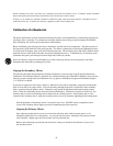
cal element that may need to be adjusted, or is possible, is the
tilt of the secondary mirror.
of your telescope you will need a light source. A bright star
al since there is a minimal amount of atmospheric distortion. Make
ith an optional motor drive) is on so that you won’t have to
r. Or, if you do not want to power up your telescope, you can use
relative to the celestial pole means that it moves very little thus
to manually track it.
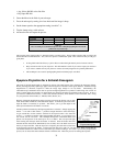
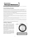
Figure 7-3
The three collimation screws are located on the front of the secondary mirror housing.
The optical performance of your telescope is directly related to
telescope was collim
the telescope is dropp
collimated. The only opti
To check the collimation
near the zenith is ide
sure that tracking (w
manually track the sta
Polaris. Its position
eliminating the need
40