


WHITE
WIRE
Adaptor Installation: - Continued
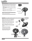
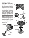
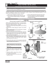
Step 14e. Align the four screw holes on the cap with
the holes on the light kit adaptor plate, using the four
(4) screws that you earlier removed from the light kit
adaptor assembly (see step 11c) and insert the four
(4) screws, attaching the cap to the bottom of the fan
as shown in Figure #10 on this page. Then tighten all
four (4) screws with the provided screwdriver.
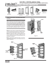
NOTE: Locate and open the box for the light kit that
you are installing on the fan and locate the installation
instructions. If the installation instructions refer to
attaching the light kit by screwing the center stem in
to the bottom of the fan, switch housing cap or that
the light kit is mounted by screw the center stem into
the bottom of the fan, it may look like the light kit as
shown in Figure # 12. You will need to use the switch
housing cap that has been provided in the box as
shown in Figure #11 during the installation of the light
kit. Otherwise, skip to step 14g.
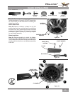
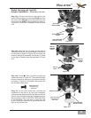
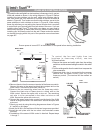
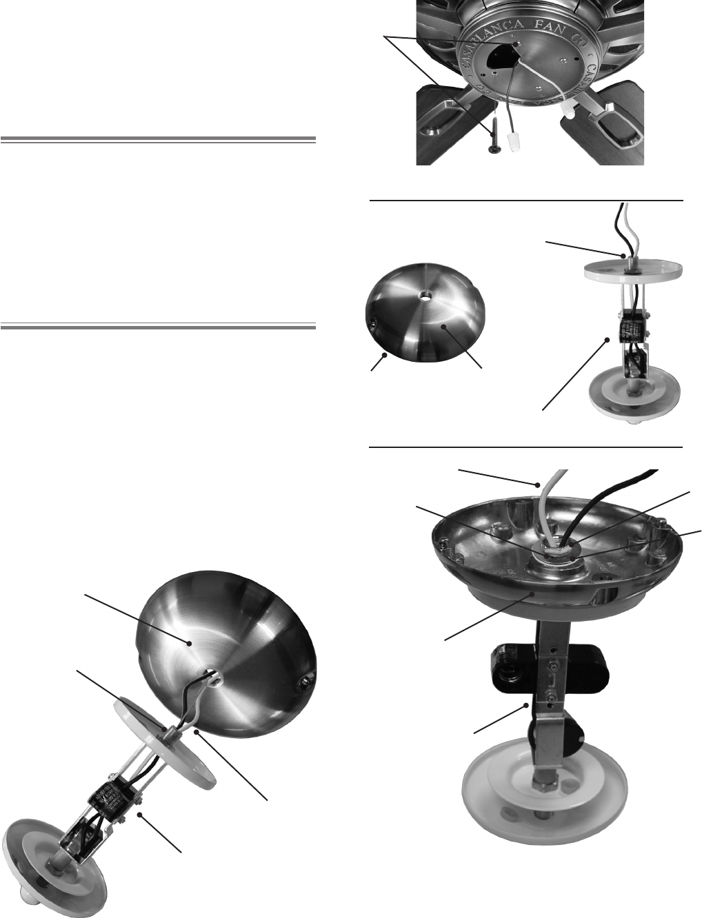
Step 14f. Locate the switch housing cap as shown in
Figure #11. Then attach the light xture to the switch
housing cap by rst threading the BLACK and WHITE
wires through the hole in the center of the switch
housing cap, also as shown in Figure #13, and then
screw the light kit xture to the bottom of the switch
housing cap by screwing the center stem of the light
xture into the bottom switch housing cap as shown
in Figures # 13 and #14. Secure the light kit to the
switch housing by placing the lock washer and hex
nut you removed from the light kit onto the center
stem and screw on rmly.
Figure #10
SWITCH HOUSING
CAP
CENTER STEM
Figure #11
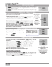
Figure #12
CENTER STEM
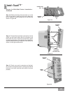
Figure #14
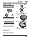
SWITCH HOUSING
CAP
CENTER STEM
LIGHT FIXTURE
{Example Photo}
WIRES
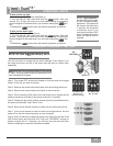
Figure #13
SWITCH HOUSING
CAP
CENTER STEM
LIGHT FIXTURE
{Example Photo}
WIRES
HEX NUT
WASHER